


- Out-of-Stock


This gearmotor is a powerful 12V brushed DC motor with a 30:1 metal gearbox and an integrated quadrature encoder that provides a resolution of 64 counts per revolution of the motor shaft, which corresponds to 1920 counts per revolution of the gearbox’s output shaft. These units have a 0.61"-long, 6 mm-diameter D-shaped output shaft. This gearmotor is also available without an encoder.

free shipping in Poland for all orders over 500 PLN

If your payment will be credited to our account by 11:00

Each consumer can return the purchased goods within 14 days
This powerful brushed DC gearmotor is available in six different gear ratios and features an integrated quadrature encoder with 64 counts per revolution (CPR) of the motor shaft. The motor and encoder portion is available by itself (no gearbox), and versions without the encoder are also available.
| Gear Ratio | No-Load Speed @ 12 V | Stall Torque @ 12 V | Stall Current @ 12 V | 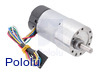 With Encoder |  Without Encoder |
|---|---|---|---|---|---|
| 1:1 | 11,000 RPM | 5 oz-in | 5 A | motor without gearbox | |
| 19:1 | 500 RPM | 84 oz-in | 5 A | 37Dx68L mm | 37Dx52L mm |
| 30:1 | 350 RPM | 110 oz-in | 5 A | 37Dx68L mm | 37Dx52L mm |
| 50:1 | 200 RPM | 170 oz-in | 5 A | 37Dx70L mm | 37Dx54L mm |
| 70:1 | 150 RPM | 200 oz-in | 5 A | 37Dx70L mm | 37Dx54L mm |
| 100:1 | 100 RPM | 220 oz-in | 5 A | 37Dx73L mm | 37Dx57L mm |
| 131:1 | 80 RPM | 250 oz-in | 5 A | 37Dx73L mm | 37Dx57L mm |
Note: Stalling or overloading gearmotors can greatly decrease their lifetimes and even result in immediate damage. Stalls can also result in rapid (potentially on the order of seconds) thermal damage to the motor windings and brushes; a general recommendation for brushed DC motor operation is 25% or less of the stall current.
These motors are intended for use at 12 V, though in general, these kinds of motors can run at voltages above and below the nominal voltage (they can begin rotating at voltages as low as 1 V). Lower voltages might not be practical, and higher voltages could start negatively affecting the life of the motor.
These gearmotors are functionally identical to the previous versions we carried without end caps (they use the same motor, encoder, and gearboxes). The black plastic end cap is easily removable if you need to access the encoder or want to slightly reduce the overall gearmotor size, but there is a little bit of base plastic that will remain, as shown in the pictures below:
Warning: Do not screw too far into the mounting holes as the screws can hit the gears. We recommend screwing no further than 3mm (1/8") into the screw hole.
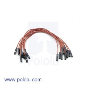
A two-channel Hall effect encoder is used to sense the rotation of a magnetic disk on a rear protrusion of the motor shaft. The quadrature encoder provides a resolution of 64 counts per revolution of the motor shaft when counting both edges of both channels. To compute the counts per revolution of the gearbox output, multiply the gear ratio by 64. The motor/encoder has six color-coded, 11″ (28 cm) leads terminated by a 1×6 female header with a 0.1″ pitch, as shown in the main product picture. This header works with standard 0.1″ male headers and our male jumper and precrimped wires. If this header is not convenient for your application, you can pull the crimped wires out of the header or cut the header off. The following table describes the wire functions:
| Color | Function |
|---|---|
| Red | motor power (connects to one motor terminal) |
| Black | motor power (connects to the other motor terminal) |
| Green | encoder GND |
| Blue | encoder Vcc (3.5 – 20 V) |
| Yellow | encoder A output |
| White | encoder B output |
The Hall sensor requires an input voltage, Vcc, between 3.5 and 20 V and draws a maximum of 10 mA. The A and B outputs are square waves from 0 V to Vcc approximately 90° out of phase. The frequency of the transitions tells you the speed of the motor, and the order of the transitions tells you the direction. The following oscilloscope capture shows the A and B (yellow and white) encoder outputs using a motor voltage of 12 V and a Hall sensor Vcc of 5 V:
By counting both the rising and falling edges of both the A and B outputs, it is possible to get 64 counts per revolution of the motor shaft. Using just a single edge of one channel results in 16 counts per revolution of the motor shaft, so the frequency of the A output in the above oscilloscope capture is 16 times the motor rotation frequency.
| Size: | 37D x 68L mm1 |
|---|---|
| Weight: | 215 g |
| Shaft diameter: | 6 mm |
| Gear ratio: | 30:1 |
|---|---|
| Free-run speed @ 12V: | 350 rpm |
| Free-run current @ 12V: | 300 mA |
| Stall current @ 12V: | 5000 mA |
| Stall torque @ 12V: | 110 oz·in |
| Free-run speed @ 6V: | 175 rpm2 |
| Free-run current @ 6V: | 250 mA2 |
| Stall current @ 6V: | 2500 mA2 |
| Stall torque @ 6V: | 55 oz·in2 |
| Lead length: | 11 in |
Data sheet
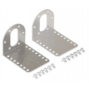
A pair of aluminum brackets with holes for M3 screws for 37D mm gear motors. Pololu 1084
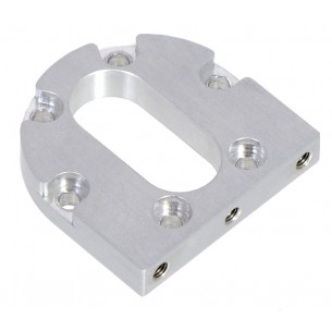
Aluminum bracket with holes for M3 screws for 37D mm gear motors. Pololu 1995
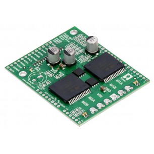
This shield makes it easy to control two high-power DC motors with your Arduino or Arduino-compatible board. Its dual robust VNH5019 motor drivers operate from 5.5 to 24 V and can deliver a continuous 12 A (30 A peak) per motor, or a continuous 24 A (60 A peak) to a single motor connected to both channels. Pololu 2507
No product available!
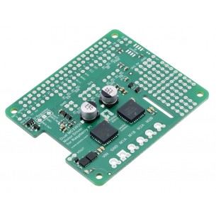
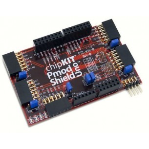
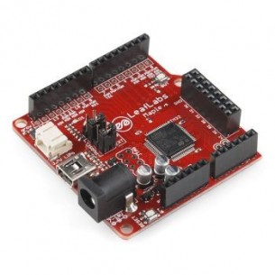
This add-on board enables a Raspberry Pi B+, Pi A+, Pi 2 or Pi 3 to drive a pair of brushed DC motors. Its dual MC33926 motor drivers operate from 5 V to 28 V and can deliver a continuous 3 A (5 A peak) per motor. The default pin mappings make it easy to get started using our provided software, but the board also exposes most of the driver chips’ I/O pins for more specialized applications.
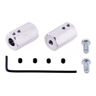
These 20 mm long aluminum adapters convert a 6 mm diameter shaft to a 12 mm hex shaft that is compatible with many common hobby RC wheels. Pololu 2686
Digital Design using Digilent FPGA Boards 2nd Edition, 2012; Richard E. Haskell & Darrin M. Hanna --- EDU
No product available!
No product available!
No product available!
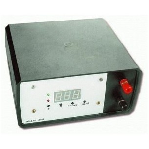
Frequency Synthesizer for RF Personal Communications, 1.2 GHz, Supply voltage 2.7V to 5.5V, National, TSSOP20
No product available!
No product available!
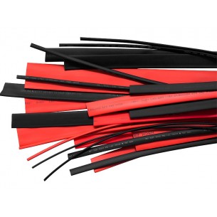
EXTREME heat shrink tubing for electrical and mechanical insulation, diameter against shrinkage 5.0 mm; diameter after shrinkage 1.5 mm, a set of 10 pieces with a length of 1 meter
No product available!
No product available!
No product available!
No product available!
No product available!
No product available!
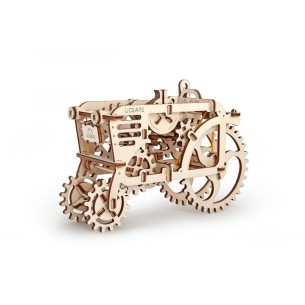
The UGEARS tractor is a rattling greeting from centuries past. No electronics - just plywood, a rubber band motor, and tons of fun! UGears 70003
No product available!
No product available!
No product available!
No product available!
No product available!
This gearmotor is a powerful 12V brushed DC motor with a 30:1 metal gearbox and an integrated quadrature encoder that provides a resolution of 64 counts per revolution of the motor shaft, which corresponds to 1920 counts per revolution of the gearbox’s output shaft. These units have a 0.61"-long, 6 mm-diameter D-shaped output shaft. This gearmotor is also available without an encoder.