


- Obecnie brak na stanie


LSM303DLHC 3D Compass and Accelerometer Carrier with Voltage Regulator
LSM303DLHC 3D Compass and Accelerometer Carrier with Voltage Regulator
The LSM303DLHC combines a digital 3-axis accelerometer and 3-axis magnetometer into a single package that is ideal for making a tilt-compensated compass. The six independent readings, whose sensitivities can be set in the ranges of Âą2 to Âą16 g and Âą1.3 to Âą8.1 gauss, are available through an IÂ?C interface. The carrier board operates from 2.5 to 5.5 V and has a 0.1" pin spacing.
Clearance: This board is being replaced by the newer LSM303D carrier.
Clearance: This board is being replaced by the newer LSM303D carrier, which offers several improvements over this product, including a wider magnetic sensing range and the option of using an SPI interface rather than IÂ?C. The LSM303D carrier is not pin-compatible with earlier LSM303 carriers like the LSM303DLHC and LSM303DLM.
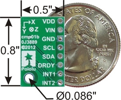 |
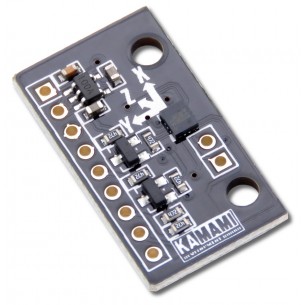
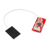
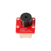
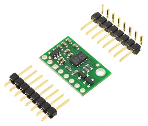
This board is a compact (0.5" A— 0.8") breakout board for ST’s LSM303DLHC 3-axis accelerometer and 3-axis magnetometer; we therefore recommend careful reading of the LSM303DLHC datasheet (629k pdf) before using this product. The LSM303DLHC is a great IC, but its small package makes it difficult for the typical student or hobbyist to use. It also operates at voltages below 3.6 V, which can make interfacing difficult for microcontrollers operating at 5 V. This carrier board addresses these issues by incorporating additional electronics, including a 3.3 V voltage regulator and level-shifting circuits, while keeping the overall size as compact as possible. The board ships fully populated with its SMD components, including the LSM303DLHC, as shown in the product picture.
Compared to the LSM303DLH and LSM303DLM used on our original compass and accelerometer carrier boards, the LSM303DLHC features improved magnetic sensing resolution and a wider acceleration measurement range (Âą2g to Âą16g). This LSM303DLHC carrier is 0.1" shorter than the earlier boards while remaining pin-compatible, although changes in IÂ?C addresses and configuration registers mean that code written to interface with an LSM303DLH or LSM303DLM might need to be modified to work with an LSM303DLHC.
The LSM303DLHC has many configurable options, including dynamically selectable sensitivities for the accelerometer and magnetometer, a choice of output data rates, and two independently-programmable external inertial interrupt pins. The magnetometer and accelerometer can be individually turned on and off to save power. The six independent magnetic and acceleration readings (sometimes called 6DOF) are available through an IÂ?C/TWI interface and can be used for many applications, including making a tilt-compensated compass that can be used to determine headings regardless of how the board is inclined (ST provides an application note (1MB pdf) that explains the details of making one).
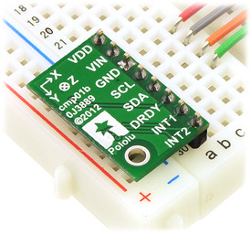
The carrier board includes a low-dropout linear voltage regulator that provides the 3.3 V required by the LSM303, which allows the sensor to be powered from a 2.5–5.5 V supply. The regulator output is available on the VDD pin and can supply almost 150 mA to external devices. The breakout board also includes a circuit that shifts the IÂ?C clock and data lines to the same logic voltage level as the supplied VIN, making it simple to interface the board with 5 V systems, and the board’s 0.1" pin spacing makes it easy to use with standard solderless breadboards and 0.1" perfboards.
For sensor fusion applications, our MinIMU-9 v2 and AltIMU-10 inertial measurement units combine the LSM303DLHC with an L3GD20 3-axis gyro on a single board, providing nine independent readings that can be used to calculate an absolute orientation. The AltIMU-10 also includes an LPS331AP pressure sensor that can be used to calculate altitude.
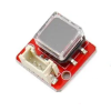
An 8A—1 strip of 0.1" header pins and an 8A—1 strip of 0.1" right-angle header pins are included, as shown in the picture below. You can solder the header strip of your choice to the board for use with custom cables or solderless breadboards, or you can solder wires directly to the board itself for more compact installations.
 |
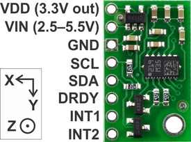
A minimum of four connections are necessary to use the LSM303DLHC: VIN, GND, SCL, and SDA. VIN should be connected to a 2.5–5.5 V source, GND to 0 volts, and SCL and SDA should be connected to an I�C bus operating at the same logic level as VIN. (Alternatively, if you are using the board with a 3.3 V system, you can leave VIN disconnected and bypass the built-in regulator by connecting 3.3 V directly to VDD.)
|
|
| PIN | Description |
|---|---|
| VDD | 3.3 V regulator output or low-voltage logic power supply, depending on VIN. When VIN is supplied and greater than 3.3 V, VDD is a regulated 3.3 V output that can supply up to approximately 150 mA to external components. Alternatively, when interfacing with a 2.5–3.3 V system, VIN can be left disconnected and power can be supplied directly to VDD. Never supply voltage to VDD when VIN is connected, and never supply more than 3.6 V to VDD. |
| VIN | This is the main 2.5–5.5 V power supply connection. The SCL and SDA level shifters pull the I�C bus high bits up to this level. |
| GND | The ground (0 V) connection for your power supply. Your IÂ?C control source must also share a common ground with this board. |
| SCL | Level-shifted IÂ?C clock line: HIGH is VIN, LOW is 0 V |
| SDA | Level-shifted IÂ?C data line: HIGH is VIN, LOW is 0 V |
| DRDY | Magnetometer data ready indicator, a 3.3V-logic-level output. HIGH (3.3 V) indicates magnetometer data can be read. LOW (0 V) indicates the magnetometer is writing new data to the data registers. This output is not level-shifted. |
| INT1 | Inertial interrupt 1, a 3.3V-logic-level output. This output is not level-shifted. |
| INT2 | Inertial interrupt 2, a 3.3V-logic-level output. This output is not level-shifted. |
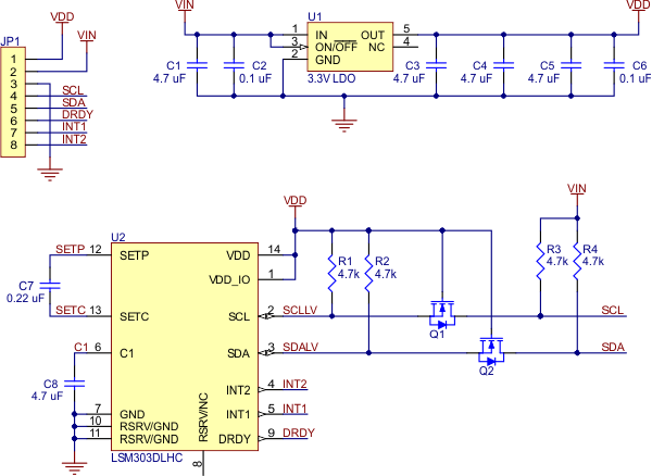 |
The above schematic shows the additional components the carrier board incorporates to make the LSM303 easier to use, including the voltage regulator that allows the board to be powered from a single 2.5–5.5 V supply and the level-shifter circuit that allows for I�C communication at the same logic voltage level as VIN.
The LSM303DLHC readings can be queried and the device can be configured through the IÂ?C bus. The module acts as two chained IÂ?C slave devices, with the accelerometer and magnetometer clock and data lines tied together to the same IÂ?C bus to ease communication. Additionally, level shifters on the IÂ?C clock (SCL) and data lines (SDA) enable IÂ?C communication with microcontrollers operating at the same voltage as VIN (2.5–5.5V). A detailed explanation of the protocol can be found in the LSM303DLHC datasheet (629k pdf), and more detailed information about IÂ?C in general can be found in NXP’s IÂ?C-bus specification (371k pdf).
The accelerometer and the magnetometer have separate 7-bit slave addresses on the IÂ?C bus. The magnetometer’s slave address is fixed to 0011110b and the accelerometer’s slave address is fixed to 0011001b.
In our tests of the board, we were able to communicate with the chip at clock frequencies up to 400 kHz; higher frequencies might work but were not tested. The chip itself and carrier board do not meet of some requirements to make the device compliant with IÂ?C fast-mode. It is missing 50 ns spike suppression on the clock and data lines, and additional pull-ups on the clock and data lines might also be necessary to achieve compliant signal timing characteristics.
The datasheet provides all the information you need to use this sensor, but picking out the important details can take some time. Here are some pointers for communicating with and configuring the LSM303DLHC that we hope will get you up and running a little bit faster:
 |
L3GD20 3-Axis Gyro Carrier with Voltage Regulator |
 |
MinIMU-9 v2 Gyro, Accelerometer, and Compass (L3GD20 and LSM303DLHC Carrier) |
 |
Female Crimp Pins for 0.1" Housings 100-Pack |
Producent BTC Korporacja sp. z o. o. Lwowska 5 05-120 Legionowo Polska sprzedaz@kamami.pl 22 767 36 20
Osoba odpowiedzialna BTC Korporacja sp. z o. o. Lwowska 5 05-120 Legionowo Polska sprzedaz@kamami.pl 22 767 36 20
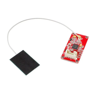
KAmodLSM6DS3 to moduł pozwalający na pomiar przyspieszenia oraz wartości prędkości kątowej. Ma wbudowany stabilizator napięcia oraz translatory poziomów na liniach SDA/SCL, dzięki czemu może być wykorzystany w systemach zasilanych napięciem 2,5-5,5V
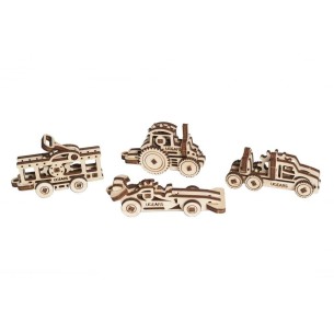
Model drewniany UGears U-9 Grand Prix to nie tylko okazja do zabawy, ale i głębokiego zrozumienia mechaniki i historii motoryzacji. Z jego bogatymi detalami, zaawansowaną mechaniką i zjawiskowym designem, model zapewnia godziny kreatywnej zabawy i edukacji. To doskonały wybór dla każdego, kto chce poczuć emocje związane z dawnymi wyścigami samochodowymi. UGears 70044
Brak towaru
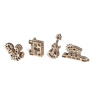
UGears U-Fidgety Kreatywność to nie tylko zestaw mechanicznych modeli do składania, ale także narzędzie edukacyjne i forma relaksu, idealne dla osób w różnym wieku. Zestaw łączy w sobie funkcjonalność, estetykę i wartość edukacyjną, stając się doskonałym wyborem zarówno jako prezent, jak i jako sposób na kreatywne spędzenie czasu. UGears 70041
Brak towaru
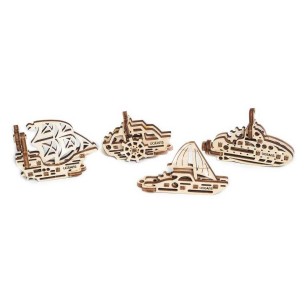
Zestaw UGears U-Fidgety Samoloty to perfekcyjny wybór dla osób w różnym wieku zainteresowanych mechaniką i modelarstwem. Dzięki wysokojakościowej sklejce i łatwości montażu, to nie tylko zabawka, ale i edukacyjne narzędzie. Modele są nie tylko funkcjonalne, ale również estetyczne, co sprawia, że są idealnym prezentem i dekoracją. UGears 70035
Brak towaru
Zestaw 4 miniaturowych modeli do samodzielnego składania to unikalne, mechaniczne zabawki wykonane ze sklejki, które rozwijają koncentrację i uwagę, służą jako oryginalne breloczki do kluczy lub dekoracje biurka, stanowiąc jednocześnie doskonały pomysł na prezent dla osób w każdym wieku. UGears 70033
Brak towaru
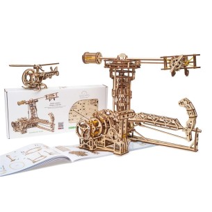
Przenieś się w świecie lotnictwa i zrealizuj swoje marzenia o lataniu z zestawem "Awiator" od UGEARS. Skomplikowany, lecz fascynujący mechanizm sterowania oraz doskonała jakość materiałów sprawią, że spędzisz niezapomniane chwile, opanowując umiejętności pilotażu. UGears 70053
Brak towaru
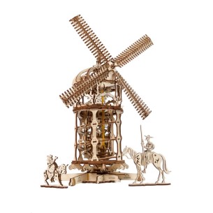
Odkryj złożoną mechanikę i bogatą historię, zanurzając się w montaż i eksplorację modelu "Wieża-Młyn Wiatrowy" od UGears. To więcej niż tylko model, to prawdziwa podróż przez wieki i kontynenty. UGears 70055
Brak towaru
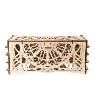
Pudełko na karty od UGEARS to nie tylko funkcjonalny organizer, ale również piękny element dekoracyjny Twojego domu. Możesz skoncentrować się na grze, nie martwiąc się bałaganem na stole. Zacznij przygodę z UGEARS i zobacz, jak można połączyć świat mechaniki z pasją do gier. UGears 70068
Brak towaru
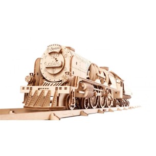
Lokomotywa z tendrem V-Ekspres od UGEARS to model, który oferuje zarówno estetyczne doświadczenie, jak i edukacyjną wartość, sprawiając, że jest to idealny wybór dla miłośników mechaniki, historii i podróży. UGears 70058
Brak towaru
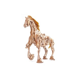
Model "Koń-mechanoid" od UGears to mechaniczne połączenie natury z technologią, inspirowane konnymi podróżami, wykonane z precyzyjnie wyciętej sklejki, które w ruchu odzwierciedla realistyczne ruchy konia. UGears 70054
Brak towaru
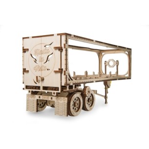
Naczepa do modelu "Ciągnik VM-03" od UGEARS, wykonana z wysokiej jakości sklejki, wzbogaca doświadczenie związane z kierowaniem ciężarówką, oferując realistyczną i funkcjonalną konstrukcję, którą można także wykorzystać jako oryginalny element dekoracyjny. UGears 70057
Brak towaru
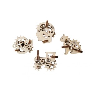
UGears U-Fidgety Trybiki to zestaw czterech miniaturowych modeli z wysokiej jakości sklejki, które symbolizują różne wartości i mogą służyć jako breloczki do kluczy, stymulując przy tym koncentrację i kreatywność użytkownika. UGears 70029
Brak towaru
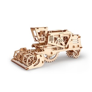
Kombajn żniwny UGEARS to precyzyjnie wykonany, mechaniczny model składany z wysokiej jakości sklejki, który naśladuje ruch prawdziwej maszyny, wyposażony w gumowy silnik i ukryty schowek, a do jego montażu dołączona jest ilustrowana instrukcja w 11 językach. UGears 70010
Brak towaru
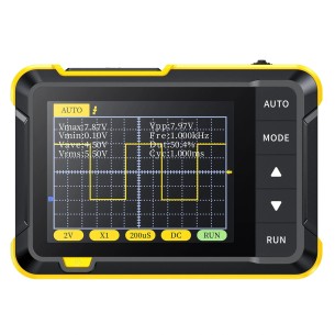
Cyfrowy oscyloskop o kompaktowych wymiarach. Oferuje pasmo częstotliwości o szerokości 200 kHz i częstotliwość próbkowania 2,5 MS/s. Wyposażony w kolorowy wyświetlacz o przekątnej 2,8" i rozdzielczości 320x240 pikseli. Fnirsi DSO152
Brak towaru
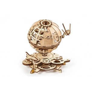
UGears Globus to nie tylko model do składania, ale także fascynujący obiekt, który inspiruje do nauki i odkrywania świata. Jest to idealny prezent dla osób w każdym wieku, interesujących się geografią, podróżami, a także dla tych, którzy cenią sobie wyjątkowe i oryginalne dekoracje do domu czy biura. UGears 70128
Brak towaru
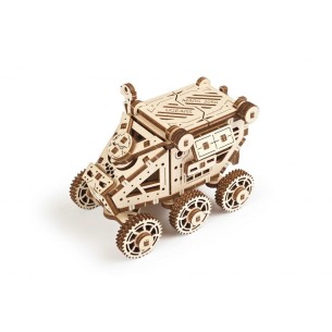
Łazik Marsjański od UGEARS to futurystyczny, sześciokołowy model inspirowany najnowszymi osiągnięciami w dziedzinie kosmonautyki, który charakteryzuje się zwrotnością, otwieranym dachem do przechowywania małych przedmiotów, kamerą dokumentującą warunki i panelami słonecznymi zapewniającymi zasilanie. UGears 70165
Brak towaru
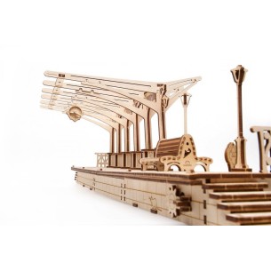
UGears Peron to idealny wybór dla pasjonatów modelarstwa, miłośników kolei oraz każdego, kto ceni sobie wyjątkowe przedmioty z duszą. Model ten stanowi nie tylko atrakcyjny element dekoracyjny, ale również zapewnia godziny kreatywnej zabawy i satysfakcji z własnoręcznie zmontowanego dzieła. UGears 70013
Brak towaru
LSM303DLHC 3D Compass and Accelerometer Carrier with Voltage Regulator