


186,71 zł Netto
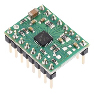
Wysokoprądowy sterownik silnika D 36v15 Pololu umożliwia sterowanie silnikami DC w systemach do 50 V przy zachowaniu niewielkich wymiarów i prostego interfejsu sterującego. Moduł znajduje zastosowanie w projektach wymagających prądu do 15 A bez radiatora oraz możliwości zwiększenia wydajności prądowej poprzez dodatkowe chłodzenie. Pololu 760
Pololu High-Power Motor Driver 36v15 przeznaczony do dwukierunkowego sterowania jednym szczotkowym silnikiem prądu stałego w aplikacjach wysokonapięciowych. Moduł wykorzystuje dyskretny mostek H oparty na tranzystorach MOSFET typu N i obsługuje szeroki zakres napięcia zasilania od 5,5 V do 50 V, co umożliwia zastosowanie w systemach 24 V oraz 36 V.
Kompaktowa płytka o wymiarach 1,8 × 0,8 cala umożliwia dostarczanie do 15 A prądu ciągłego bez radiatora, a przy dodatkowym chłodzeniu do około 20 A. Prosty interfejs sterowania wymaga jedynie dwóch linii sygnałowych (PWM i DIR), co ułatwia integrację z mikrokontrolerami i systemami nadrzędnymi. Sterownik obsługuje tryby sign-magnitude oraz locked-antiphase, pozwalając na elastyczny dobór metody regulacji prędkości i kierunku obrotów.
Układ zapewnia detekcję zwarć, spadków napięcia oraz przegrzania, sygnalizowanych na wyjściach FF1 i FF2. Brak sprzętowych zabezpieczeń nadprądowych i temperaturowych wymaga odpowiedniego doboru silnika, zapewnienia chłodzenia oraz w aplikacjach granicznych stosowania zewnętrznego monitorowania prądu. Rozwiązanie sprawdza się w robotach mobilnych, napędach o dużej mocy i projektach prototypowych wymagających wysokiego napięcia zasilania.
Cechy
Producent BTC Korporacja sp. z o. o. Lwowska 5 05-120 Legionowo Polska sprzedaz@kamami.pl 22 767 36 20
Osoba odpowiedzialna BTC Korporacja sp. z o. o. Lwowska 5 05-120 Legionowo Polska sprzedaz@kamami.pl 22 767 36 20
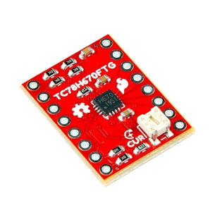
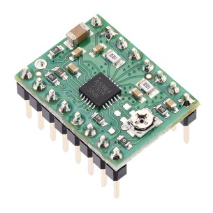
Kompaktowy sterownik, który umożliwia precyzyjne sterowanie bipolarnymi silnikami krokowymi. Oferuje dużą precyzję ruchu dzięki możliwości sterowania silnikiem krokowym z rozdzielczością do 1/128 kroku oraz dwa interfejsy sterujące - sterowanie krokowe typu clock-in oraz komendy szeregowe. SparkFun ROB-25167
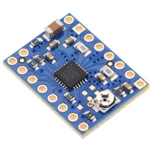
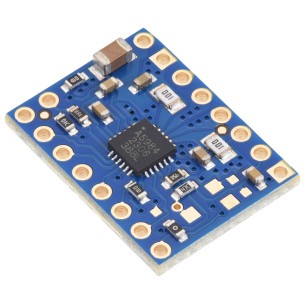
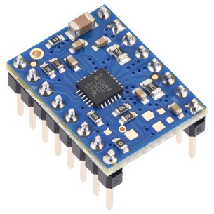
Kompaktowy i wydajny moduł przeznaczony do precyzyjnego sterowania bipolarnymi silnikami krokowymi, oferujący mikrostepping do 1/32 kroku oraz maksymalny prąd do 2 A w trybie szczytowym. Dzięki zaawansowanym funkcjom, takim jak algorytm QuietStep (APFD), wbudowane zabezpieczenia oraz kompatybilność pinowa z A4988, doskonale sprawdzi się w projektach hobbystycznych, edukacyjnych i przemysłowych. Wersja Blue Edition z czterowarstwową płytką i miedzią 2 oz zapewnia lepsze odprowadzanie ciepła, zwiększając niezawodność pracy nawet przy wyższych obciążeniach. Pololu 5340
Kompaktowy i wydajny moduł przeznaczony do precyzyjnego sterowania bipolarnymi silnikami krokowymi, oferujący mikrostepping do 1/32 kroku oraz maksymalny prąd do 2 A w trybie szczytowym. Dzięki zaawansowanym funkcjom, takim jak algorytm QuietStep (APFD), wbudowane zabezpieczenia oraz kompatybilność pinowa z A4988, doskonale sprawdzi się w projektach hobbystycznych, edukacyjnych i przemysłowych. Wersja Blue Edition z czterowarstwową płytką i miedzią 2 oz zapewnia lepsze odprowadzanie ciepła, zwiększając niezawodność pracy nawet przy wyższych obciążeniach. Pololu 5341
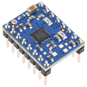
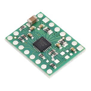
Sterownik do bipolarnych silników krokowych z interfejsem STEP/DIR, mikrokroki do 1/16 oraz regulacja prądu za pomocą potencjometru, współpraca z logiką 3,3 V i 5 V, wersja bez przylutowanych złączy. Pololu 5342
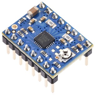
Sterownik do bipolarnych silników krokowych z interfejsem STEP/DIR, mikrokroki do 1/16 oraz regulacja prądu za pomocą potencjometru, współpraca z logiką 3,3 V i 5 V, przylutowane złącza goldpin. Pololu 5343
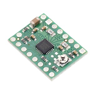
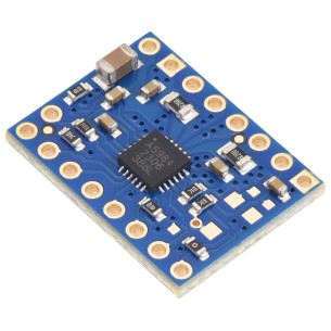
Sterownik do bipolarnych silników krokowych z interfejsem STEP/DIR, mikrokroki do 1/16 oraz maksymalny prąd do 1,5 A przy 5 V lub 1 A przy 3,3 V, wersja bez przylutowanych złączy. Pololu 5344
Sterownik do bipolarnych silników krokowych z interfejsem STEP/DIR, mikrokroki do 1/16, przylutowane złącza goldpin oraz maksymalny prąd do 1,5 A przy 5 V lub 1 A przy 3,3 V. Pololu 5345
Sterownik do bipolarnych silników krokowych z interfejsem STEP/DIR, mikrokroki do 1/16 oraz maksymalny prąd do 1 A przy logice 5 V lub 660 mA przy 3,3 V. Pololu 5346
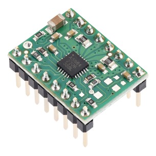
Sterownik silnika krokowego oparty na układzie A5984, z przylutowanymi złączami goldpin, przeznaczony do sterowania bipolarnymi silnikami krokowymi w projektach elektronicznych i robotycznych. Pololu 5347
Sterownik silnika krokowego A5984 do silników bipolarnych, zasilanie 8–40 V, stały limit prądu 750 mA przy 5 V lub 500 mA przy 3,3 V, mikrokrok do 1/32 oraz interfejs STEP/DIR. Pololu 5348
Sterownik silnika krokowego A5984 do silników bipolarnych, zasilanie 8–40 V, stały limit prądu 750 mA przy 5 V lub 500 mA przy 3,3 V, mikrokrok do 1/32 oraz interfejs STEP/DIR. Wersja z przylutowanymi złączami goldpin. Pololu 5349
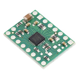
Sterownik silnika krokowego A5984 do silników bipolarnych, zasilanie 8-40 V, stały limit prądu 500 mA przy 5 V lub 330 mA przy 3,3 V, mikrokrok do 1/32 oraz interfejs STEP/DIR. Pololu 5350
Sterownik silnika krokowego A5984 do silników bipolarnych, zasilanie 8-40 V, stały limit prądu 500 mA przy 5 V lub 330 mA przy 3,3 V, mikrokrok do 1/32 oraz interfejs STEP/DIR. Wersja z przylutowanymi złączami goldpin. Pololu 5351
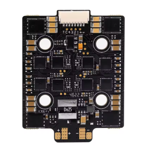
Kompaktowy i wydajny regulator prędkości ESC przeznaczony do modeli RC i wyścigów FPV, obsługujący akumulatory LiPo 4S–8S oraz stały prąd 60 A (chwilowy do 70 A). Dzięki standardowi montażowemu 20x20 mm, zapewnia trwałość, niezawodność i łatwą integrację nawet w ograniczonej przestrzeni. Zastosowanie oprogramowania AM32 i zmiennej częstotliwości PWM gwarantuje wysoką precyzję oraz płynną pracę silników w każdych warunkach. F60A mini
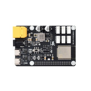
Waveshare DDSM Driver HAT (B) to zaawansowany sterownik silników piastowych DDSM400, oparty na ESP32, z obsługą komunikacji przewodowej (USB, UART) i bezprzewodowej (WiFi, ESP-NOW). Umożliwia sterowanie do 6 silników z wykorzystaniem poleceń JSON i integrację z Raspberry Pi, co czyni go odpowiednim rozwiązaniem dla robotyki mobilnej i projektów systemów wielosilnikowych.
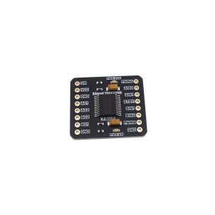
Dwukanałowy sterownik KAmod Motor Driver TB6612FNG z mostkami H MOSFET umożliwia precyzyjne sterowanie silnikami DC i krokowymi z częstotliwością PWM do 100 kHz. Kompaktowa konstrukcja, szeroki zakres napięcia i zabezpieczenia czynią moduł odpowiednim do projektów mobilnych, robotyki i automatyki.
Wysokoprądowy sterownik silnika D 36v15 Pololu umożliwia sterowanie silnikami DC w systemach do 50 V przy zachowaniu niewielkich wymiarów i prostego interfejsu sterującego. Moduł znajduje zastosowanie w projektach wymagających prądu do 15 A bez radiatora oraz możliwości zwiększenia wydajności prądowej poprzez dodatkowe chłodzenie. Pololu 760