


- Obecnie brak na stanie
")

")


darmowa wysyłka na terenie Polski dla wszystkich zamówień powyżej 500 PLN

Jeśli Twoja wpłata zostanie zaksięgowana na naszym koncie do godz. 11:00

Każdy konsument może zwrócić zakupiony towar w ciągu 14 dni bez zbędnych pytań
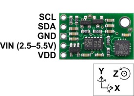
The Pololu MinIMU-9 v2 is an inertial measurement unit (IMU) that packs an L3GD20 3-axis gyro and an LSM303DLHC 3-axis accelerometer and 3-axis magnetometer onto a tiny 0.8” × 0.5” board. An I2C interface accesses nine independent rotation, acceleration, and magnetic measurements that can be used to calculate the sensor’s absolute orientation. The MinIMU-9 v2 board includes a voltage regulator and a level-shifting circuit that allows operation from 2.5 to 5.5 V, and the 0.1” pin spacing makes it easy to use with standard solderless breadboards and 0.1” perfboards.
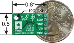 |
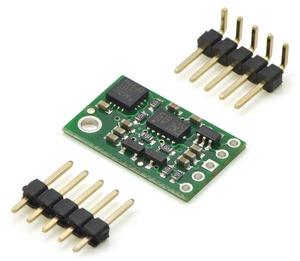
The Pololu MinIMU-9 v2 is a compact (0.8” × 0.5”) board that combines ST’s L3GD20 3-axis gyroscope and LSM303DLHC 3-axis accelerometer and 3-axis magnetometer to form an inertial measurement unit (IMU); we therefore recommend careful reading of the L3GD20 datasheet (2MB pdf) and the LSM303DLHC datasheet (629k pdf) before using this product. These sensors are great ICs, but their small packages make them difficult for the typical student or hobbyist to use. They also operate at voltages below 3.6 V, which can make interfacing difficult for microcontrollers operating at 5 V. The MinIMU-9 v2 addresses these issues by incorporating additional electronics, including a voltage regulator and a level-shifting circuit, while keeping the overall size as compact as possible. The board ships fully populated with its SMD components, including the L3GD20 and LSM303, as shown in the product picture.
The MinIMU-9 v2 offers several enhancements over our original MinIMU-9. Most noticeably, the MinIMU-9 v2 board is 0.1” smaller on each side, reducing its overall size by 25%! Compared to the LSM303DLH and LSM303DLM used on the earlier MinIMU-9 boards, the LSM303DLHC on the MinIMU-9 v2 features improved magnetic sensing resolution and a wider acceleration measurement range (±2g to ±16g). In addition, the new L3GD20 gyro uses a higher resonant frequency that makes it more resistant to audio noise and vibrations than the older L3G4200D. The MinIMU-9 v2 is pin-compatible with the original MinIMU-9, although changes in I2C addresses and configuration registers mean that code written to interface with a MinIMU-9 will need to be modified to work with a MinIMU-9 v2.
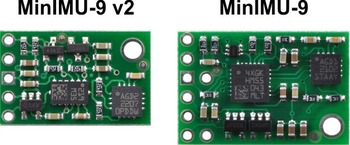 |
| Side-by-side comparison of the MinIMU-9 v2 with the original MinIMU-9. |
|---|
The L3GD20 and the LSM303DLHC have many configurable options, including dynamically selectable sensitivities for the gyro, accelerometer, and magnetometer, as well as a choice of output data rates for each sensor. The two ICs can be accessed through a shared I2C/TWI interface, allowing all three sensors to be addressed individually via a single clock line and a single data line. The nine independent rotation, acceleration, and magnetic readings (sometimes called 9DOF) provide all the data needed to make an attitude and heading reference system (AHRS). With an appropriate algorithm, a microcontroller or computer can use the data to calculate the orientation of the MinIMU-9 v2 board; the gyro can be used to very accurately track rotation on a short timescale, while the accelerometer and compass can help compensate for gyro drift over time by providing an absolute frame of reference. The respective axes of the two chips are aligned on the board to facilitate these sensor fusion calculations. (For an example of such a system using an Arduino, see the picture below and the Sample Code section at the bottom of this page.)
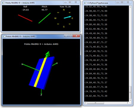 |
| Visualization of AHRS orientation calculated from MinIMU-9 readings. |
|---|
The carrier board includes a low-dropout linear voltage regulator that provides the 3.3 V required by the L3GD20 and LSM303, allowing the module to be powered from a single 2.5-5.5 V supply. The regulator output is available on the VDD pin and can supply almost 150 mA to external devices. The breakout board also includes a circuit that shifts the I2C clock and data lines to the same logic voltage level as the supplied VIN, making it simple to interface the board with 5 V systems, and the board’s 0.1” pin spacing makes it easy to use with standard solderless breadboards and 0.1” perfboards.
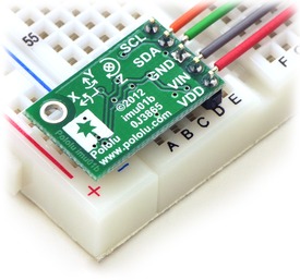
A 5×1 strip of 0.1” header pins and a 5×1 strip of 0.1” right-angle header pins are included, as shown in the picture below. You can solder the header strip of your choice to the board for use with custom cables or solderless breadboards, or you can solder wires directly to the board itself for more compact installations.
 |
A minimum of four connections are necessary to use the MinIMU-9 v2: VIN, GND, SCL, and SDA. VIN should be connected to a 2.5-5.5 V source, GND to 0 volts, and SCL and SDA should be connected to an I2C bus operating at the same logic level as VIN. (Alternatively, if you are using the board with a 3.3 V system, you can leave VIN disconnected and bypass the built-in regulator by connecting 3.3 V directly to VDD.)
|
|
| PIN | Description |
|---|---|
| SCL | Level-shifted I2C clock line: HIGH is VIN, LOW is 0 V |
| SDA | Level-shifted I2C data line: HIGH is VIN, LOW is 0 V |
| GND | The ground (0 V) connection for your power supply. Your I2C control source must also share a common ground with this board. |
| VIN | This is the main 2.5 – 5.5 V power supply connection. The SCL and SDA level shifters pull the I2C bus high bits up to this level. |
| VDD | 3.3 V regulator output or low-voltage logic power supply, depending on VIN. When VIN is supplied and greater than 3.3 V, VDD is a regulated 3.3 V output that can supply up to approximately 150 mA to external components. Alternatively, when interfacing with a 2.5 – 3.3 V system, VIN can be left disconnected and power can be supplied directly to VDD. Never supply voltage to VDD when VIN is connected, and never supply more than 3.6 V to VDD. |
The data ready and interrupt pins of the L3GD20 and the LSM303DLHC are not accessible on the MinIMU-9 v2.
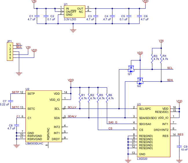 |
The above schematic shows the additional components the carrier board incorporates to make the L3GD20 and LSM303DLHC easier to use, including the voltage regulator that allows the board to be powered from a single 2.5-5.5 V supply and the level-shifter circuit that allows for I2C communication at the same logic voltage level as VIN. This schematic is also available as a downloadable pdf: MinIMU-9 v2 schematic (149k pdf).
The L3GD20 and LSM303DLHC readings can be queried and the devices can be configured through the I2C bus. The three sensors (the L3GD20 gyro and the LSM303DLHC accelerometer and magnetometer) act as slave devices on the same I2C bus (i.e. their clock and data lines are tied together to ease communication). Additionally, level shifters on the I2C clock (SCL) and data lines (SDA) enable I2C communication with microcontrollers operating at the same voltage as VIN (2.5 – 5.5V). A detailed explanation of the protocols used by each device can be found in the L3GD20 datasheet (2MB pdf) and the LSM303DLHC datasheet (629k pdf), and more detailed information about I2C in general can be found in NXP’s I2C-bus specification (371k pdf).
The gyro, accelerometer, and magnetometer each have separate slave addresses on the I2C bus. The board pulls the gyro’s SA0 pin high, setting its slave address to 1101011b. The accelerometer’s slave address is fixed to 0011001b and the magnetometer’s slave address is fixed to 0011110b.
In our tests of the MinIMU-9 v2, we were able to communicate with both chips at clock frequencies up to 400 kHz; higher frequencies might work but were not tested. The chips themselves and carrier board do not meet of some requirements to make the devices compliant with I2C fast mode. They are missing 50 ns spike suppression on the clock and data lines, and additional pull-ups on the clock and data lines might also be necessary to achieve compliant signal timing characteristics.
We have written a basic L3GD20 Arduino library and LSM303 Arduino library that make it easy to interface the MinIMU-9 with an Arduino. The libraries make it simple to configure the sensors and read their raw gyro, accelerometer, and magnetometer data.
For a demonstration of what you can do with this data, you can turn an Arduino connected to a MinIMU-9 into an attitude and heading reference system, or AHRS, with this Arduino program. It uses the data from the MinIMU-9 to calculate estimated roll, pitch, and yaw angles, and you can visualize the output of the AHRS with a 3D test program on your PC (as shown in a screenshot above). This software is based on the work of Jordi Munoz, William Premerlani, Jose Julio, and Doug Weibel.
The datasheets provide all the information you need to use the sensors on the MinIMU-9 v2, but picking out the important details can take some time. Here are some pointers for communicating with and configuring the L3GD20 and LSM303DLHC that we hope will get you up and running a little bit faster:
We carry several inertial measurement and orientation sensors. The table below compares their capabilities:
| Product Name | Sensors | Estimation | Other | |||||
| Gyros (3x) | Accels (3x) | Mag (3x) | Roll | Pitch | Yaw | Quaternion | Enclosure | |
| Pololu MinIMU-9 v2 |
 |
|
|
|||||
| CHR-UM6-LT Orientation Sensor |
|
|
|
|
|
|
|
|
| CHR-UM6 Orientation Sensor |
|
|
|
|
|
|
|
|
Download:
Osoba odpowiedzialna BTC Korporacja sp. z o. o. Lwowska 5 05-120 Legionowo Polska sprzedaz@kamami.pl 22 767 36 20
Brak towaru
Brak towaru
Brak towaru
Brak towaru
Karta pamięci SanDisk Ultra microSDHC 32 GB 100MB/s C10 to wydajny i niezawodny nośnik pamięci o dużej pojemności, oferujący szybki transfer danych, kompatybilność z różnymi urządzeniami i odporność na trudne warunki, idealny dla smartfonów, tabletów, kamer sportowych czy dronów. SanDisk SDSQUNR-032G-GN3MN
Brak towaru
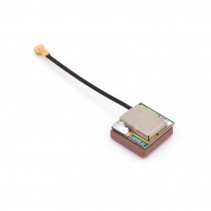
Antena z wbudowanym wzmacniaczem LNA o wysokiej czułości, do montażu w urządzeniu wykorzystującym moduł GPS. Antena ma przewód o długości 25mm, zakończony wtykiem U.FL (IPEX). Wymiary urządzenia: 9 x 9 x 4mm
Brak towaru
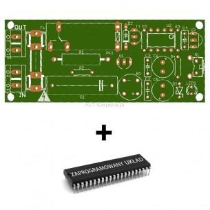
PCB i zaprogramowany układ do włącznika 230V sterowanego dowolnym pilotem na podczerwień. AVT1840 A+
Brak towaru
Brak towaru
Brak towaru
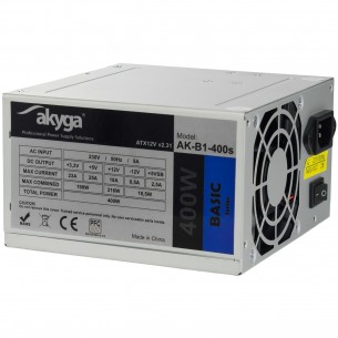
Zasilacz Akyga AK-B1-400S przeznaczony do zasilania komputerów stacjonarnych. Zgodny ze standardem ATX 2.31, moc 400W. Akyga AK-B1-400S
Brak towaru
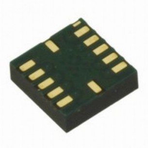
Ultra high performance digital triaxial acceleration sensor, I2C and SPI interface mode, voltage 1.62V - 3.6V, LGA12, BOSCH, RoHS
Brak towaru
Brak towaru
Brak towaru
Brak towaru
Brak towaru
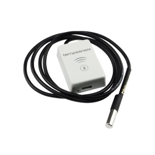
BleBox tempSensor to miniaturowy czujnik temperatury pozwalający na jej monitorowanie za pomocą WiFi. Pozwala na pomiar temperatury w zakresie od -55 do +125 stopni Celsjusza (z dokladnością do ± 0,5°C )
Brak towaru