- Obecnie brak na stanie

MMA7361L 3-Axis Accelerometer ±1.5/6g
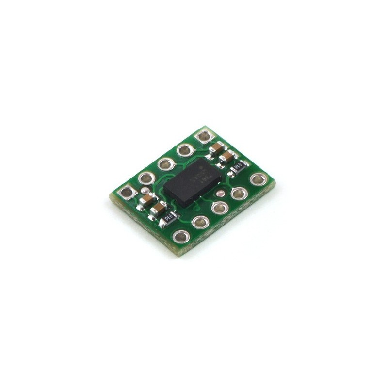
This tiny triple-axis accelerometer is a basic carrier board for the Freescale MMA7361L XYZ-axis accelerometer, a great low-g sensor with analog voltage outputs, adjustable sensitivity (±1.5 g or ±6 g), and a 0g-detect digital output that signals when the board is in free-fall. Our breakout board has the form factor of a 10-pin DIP package, which makes it easy to use with standard solderless breadboards and 0.1" perfboards, and the unit is smaller than competing products, all at a lower price. The board operates from 2.2 to 3.6 V.
Note: The MMA7361L and MMA7341L ICs on these boards have been replaced by the newer MMA7361LC and MMA7341LC, respectively. The only functional differences are a slight change to the tolerance of the zero-g Z output (both MMA7361LC and MMA7341LC) and change in the magnitude of the z-axis self-test response (MMA7341LC only).
 |
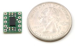
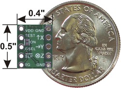
This tiny three-axis accelerometer is a breakout board for Freescale’s MMA7361L (192k pdf) and MMA7341L (195k pdf) MEMS (micro-electro-mechanical systems) low-g accelerometers; we therefore recommend careful reading the appropriate datasheet for your particular board before using this product. The MMA7361 and MMA7341 are great ICs, but their small, leadless packages makes them difficult for the typical student or hobbyist to use. This carrier board includes all of the components in the part’s recommended connection diagram and breaks the pins out to a 0.5"×0.4" (12.7×10.2 mm) 10-pin DIP form factor that is easy to use with standard solderless breadboards and 0.1" perfboards.
The two versions of this board provide different sensitivity options: the MMA7361L carrier offers selectable ±1.5g or ±6g sensitivities and the MMA7341L carrier offers selectable ±3g or ±11g sensitivities. We also sell two larger versions of this carrier board that include a 3.3V voltage regulator: the MMA7361L 3-axis accelerometer carrier with voltage regulator and the MMA7341L 3-axis accelerometer carrier with voltage regulator
 |
 |
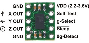
The board is powered by supplying 2.2 to 3.6 V on the VDD pin. Note that this part does not have 5V-tolerant pins, so external components (such as voltage dividers) are required when interfacing the board’s g-Select, Self Test, and Sleep pins with 5V systems. Connections to these pins are optional; the board will work with these pins disconnected as long as the sleep pin is driven high with an on-board solder bridge as described below.
The sleep pin, Sleep, is internally pulled low, which puts the board into low-power sleep mode by default. You must drive this pin high to use the board. This can be accomplished with a microcontroller I/O line if you want selective control of sleep mode, or you can make a solder bridge across the SMT jumper pads labeled “ON” on the silkscreen side of the board to connect the sleep pin to VDD and enable the board by default.
The accelerometer X, Y, and Z outputs are three separate analog voltages centered at VDD/2. Positive accelerations along an axis increase that axis’s output voltage above VDD/2 and negative accelerations decrease the output voltage below VDD/2. The outputs will always be within the range of 0 to VDD.
The sensitivity selection pin, g-Select, is internally pulled low, which selects for a default sensitivity of ±1.5g (800 mV/g) on the MMA7361L carrier and ±3g (440 mV/g) on the MMA7341L carrier. Driving the pin high selects for a sensitivity of ±6g (206 mV/g) on the MMA7361L carrier and ±11g (118 mV/g) on the MMA7341L carrier.
The 0g-Detect pin outputs high when all three axes simultaneously detect 0g, which happens when the board is in free-fall. This pin is only documented in the datasheet of the more sensitive MMA7361L IC (the MMA7341L datasheet labels this pin as “NC”), but we have found that it works on the MMA7341L at its default ±3g sensitivity. This output does not work at the ±11g sensitivity setting.
The Self Test pin is pulled low on the board and can be left disconnected.
A 10×1 strip of 0.1" header pins is included, as shown in the left picture below. These pins are not pre-installed. You can break the strip into two 5×1 sub-strips and solder them in to make a 10-pin DIP that can easily be used with solderless breadboards or 0.1" perfboards, or you can solder wires directly to the board for more compact installations. The right picture below shows the two possible board orientations when used as a 10-pin DIP (parts visible or silkscreen visible).
|
|
 |
MMA7341L 3-Axis Accelerometer ±3/11g |
 |
LPY510AL Dual-Axis (Pitch and Yaw or XZ) Gyro with ±100°/s and ±400°/s Ranges |
 |
0.100" (2.54 mm) Breakaway Male Header: 1x40-Pin, Straight |
Producent BTC Korporacja sp. z o. o. Lwowska 5 05-120 Legionowo Polska sprzedaz@kamami.pl 22 767 36 20
Osoba odpowiedzialna BTC Korporacja sp. z o. o. Lwowska 5 05-120 Legionowo Polska sprzedaz@kamami.pl 22 767 36 20
Filament firmy ROSA3D wykonany z wysokiej jakości granulatu PLA-Silk charakteryzującego się intensywną barwą oraz wyjątkowym połyskiem. Na szpuli nawinięte jest 0,8 kg filamentu o średnicy 1,75 mm. Filament ROSA3D PLA-Silk Green
Brak towaru
Filament firmy ROSA3D wykonany z wysokiej jakości granulatu PLA-Silk charakteryzującego się intensywną barwą oraz wyjątkowym połyskiem. Na szpuli nawinięte jest 0,8 kg filamentu o średnicy 1,75 mm. Filament ROSA3D PLA-Silk Gold
Brak towaru
Filament firmy ROSA3D wykonany z wysokiej jakości granulatu PLA-Silk charakteryzującego się intensywną barwą oraz wyjątkowym połyskiem. Na szpuli nawinięte jest 0,8 kg filamentu o średnicy 1,75 mm. Filament ROSA3D PLA-Silk Fuchsia
Brak towaru
Filament firmy ROSA3D wykonany z wysokiej jakości granulatu PLA-Silk charakteryzującego się intensywną barwą oraz wyjątkowym połyskiem. Na szpuli nawinięte jest 0,8 kg filamentu o średnicy 1,75 mm. Filament ROSA3D PLA-Silk Copper
Brak towaru
Filament firmy ROSA3D wykonany z wysokiej jakości granulatu PLA-Silk charakteryzującego się intensywną barwą oraz wyjątkowym połyskiem. Na szpuli nawinięte jest 0,8 kg filamentu o średnicy 1,75 mm. Filament ROSA3D PLA-Silk Blue
Brak towaru
Zestaw rozwojowy z serii M5Stack wyposażony w ESP32 i kamerę z sensorem OV2640. Dedykowany do aplikacji rozpoznawania obrazów. M5Stack U007
Brak towaru
Zestaw rozwojowy z serii M5Stack wyposażony w ESP32 WROVER i kamerę z sensorem OV2640. Dedykowany do aplikacji rozpoznawania obrazów. M5Stack U017
Brak towaru
Moduł z czarno-białym wyświetlaczem e-Paper o przekątnej 13,3" i rozdzielczości 1600x1200 px. Wyposażony w interfejs HDMI. Waveshare 13.3inch HDMI e-Paper (EU)
Brak towaru
Moduł z czarno-białym wyświetlaczem e-Paper o przekątnej 9,7" i rozdzielczości 1200x825 px. Wyposażony w interfejs HDMI. Waveshare 9.7inch HDMI e-Paper
Brak towaru
Moduł z czarno-białym wyświetlaczem e-Paper o przekątnej 10,3" i rozdzielczości 1872x1404px. Wyposażony w interfejs HDMI. Waveshare 10.3inch HDMI e-Paper
Brak towaru
Moduł z kamerą 1,26 MP (sensor MT9M114) oraz mikrokontrolerem STM32H743VI z rdzeniem ARM Cortex-M7. Pozwala na łatwą implementacje algorytmów analizy obrazu w urządzeniach wbudowanych i robotach. OpenMV Cam H7 R2
Brak towaru
Brak towaru
Płytka rozszerzeń przeznaczona do modułów głównych MicroMod. Wyposażona została w złącze Qwiic oraz dwa miejsca na przymocowanie modułów funkcyjnych. SparkFun DEV-18576
Brak towaru
GD32F303CCT6, Mikrokontroler ARM Cortex M4, SRAM: 48kb, Flash: 256kb, 120MHz, LQFP48
Brak towaru
GD32E230C8T6, Mikrokontroler ARM Cortex-M23; SRAM: 8kb; Flash: 64kb; 72MHz; LQFP48
Brak towaru
Filament firmy ROSA3D wykonany z wysokiej jakości granulatu PLA-Silk charakteryzującego się intensywną barwą oraz wyjątkowym połyskiem. Na szpuli nawinięte jest 0,8 kg filamentu o średnicy 1,75 mm. Filament ROSA3D PLA-Silk Navy Blue
Brak towaru

MMA7361L 3-Axis Accelerometer ±1.5/6g
