
- Obecnie brak na stanie


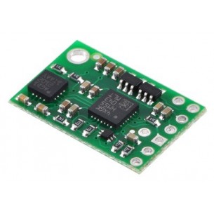
ACS715 Current Sensor Carrier 0 to 30A
ACS715 Current Sensor Carrier 0 to 30A
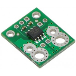
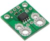
This board is a simple carrier of Allegro’s 30A ACS715 Hall effect-based linear current sensor, which offers a low-resistance (~1.2 m?) current path and electrical isolation up to 2.1 kV RMS. This version accepts a unidirectional current input up to 30 A and outputs a proportional analog voltage (133 mV/A) that measures 500 mV when the input current is zero. The typical output error is ±1.5%. It operates from 4.5 to 5.5 V and is intended for use in 5 V systems.
 |
This current sensor is a carrier board or breakout board for Allegro’s ACS715LLCTR-30A-T Hall effect-based linear current sensor; we therefore recommend careful reading of the ACS715 datasheet (574k pdf) before using this product. The sensor operates at 5 V and has an output sensitivity of 133 mV/A. The board ships fully populated with its SMD components, including the ACS715, as shown in the product picture. The following list details some of the sensor’s key features:
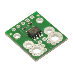
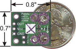
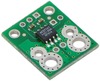
The pads are labeled on the bottom silkscreen, as shown in the picture to the right. The silkscreen also shows the direction that is interpreted as positive current flow via the +i arrow.
We sell a ±5A bidirectional version and ±30A bidirectional version version of this board; you can distinguish these versions by reading the text on the IC or by looking at the color of the X on the bottom silkscreen. This version is marked with a black X.
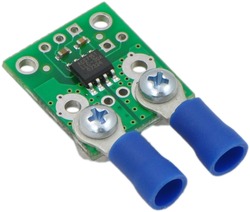 |
| ACS715 current sensor carrier with solderless ring terminal connectors (not included). |
|---|
The sensor requires a supply voltage of 4.5 – 5.5 V to be connected across the Vcc and GND pads, which are labeled on the bottom silkscreen. The sensor outputs an analog voltage that is linearly proportional to the input current. When Vcc is 5 V, this output voltage is offset by 500 mV and increases by 133 mV per amp of input current. The output voltage decreases linearly below 500 mV for currents as low as -1.5 A.
The input current can be connected to the board in a variety of ways. For low-current applications, you can solder 0.1" male header pins to the board via the small through-holes on the input-current side of the board. For higher-current applications, you can solder wires directly to the through-holes whose sizes best match your wires, or you can use solderless ring terminal connectors, as shown in the picture to the right. The large through-holes are big enough for #6 screws.
The board has two mounting holes on the logic side of the board. These mounting holes are 0.5" apart and are designed for #2 screws.
The IC has an internal filter resistance of 1.7 kΩ, and the carrier board includes a 1 nF filter capacitor, which produces a low-pass RC filter with a 90 kHz cutoff. You can improve sensing system accuracy for low-frequency sensing applictations by adding a capacitor in parallel with the integrated 1 nF capacitor across the pads marked “filter” on the bottom silkscreen (this capacitor is labeled C2b in the schematic below). The frequency F that the filter will attenuate to half its original power is given by:
F = 1 / (2đRC) = 1 / (11kΩ * (1 nF + Cf))
where Cf is the value of the capacitor added to the filter pads.
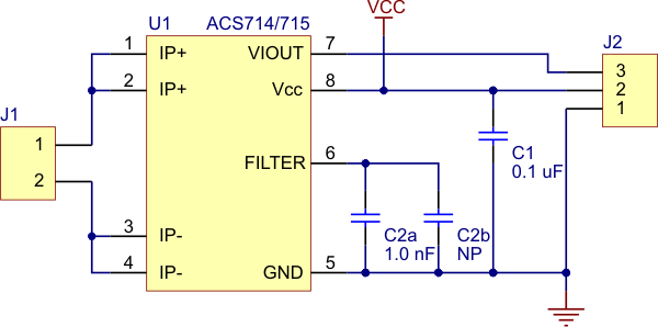 |
| Pololu ACS714/ACS715 current sensor carrier schematic diagram. |
|---|
 |
ACS714 Current Sensor Carrier -5 to +5A |
 |
ACS714 Current Sensor Carrier -30 to +30A |
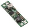 |
Pololu Step-Down Voltage Regulator D15V35F5S3 |
Producent BTC Korporacja sp. z o. o. Lwowska 5 05-120 Legionowo Polska sprzedaz@kamami.pl 22 767 36 20
Osoba odpowiedzialna BTC Korporacja sp. z o. o. Lwowska 5 05-120 Legionowo Polska sprzedaz@kamami.pl 22 767 36 20
Brak towaru
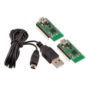
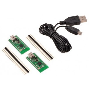
Wixel Pair (Fully Assembled) + USB Cable
Brak towaru
Brak towaru
MinIMU-9 Gyro, Accelerometer, and Compass (L3G4200D and LSM303DLM Carrier)
Brak towaru
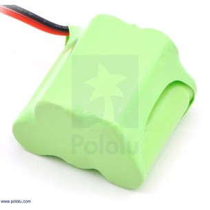
Pakiet NiMH składający się z ogniw NiMH AAA o sumarycznym napięciu 6,0 V oraz pojemności 350 mAh. Konfiguracja ogniw 3+2. Posiada konektror JR, 3-pin żeński, wymiary: 31 x 20 x 31mm, waga: 37,70g. Pololu 2244
Brak towaru
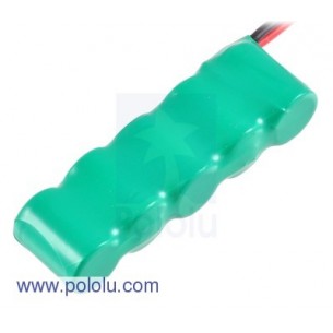
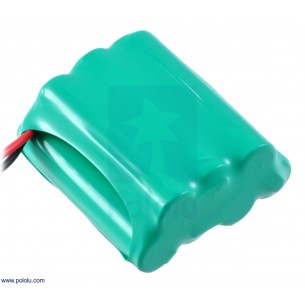
Rechargeable NiMH Battery Pack: 6.0 V, 200 mAh, 5x1 1/3-AAA Cells, JR Connector
Brak towaru
Rechargeable NiMH Battery Pack: 6.0 V, 200 mAh, 3+2 1/3-AAA Cells, JR Connector
Brak towaru
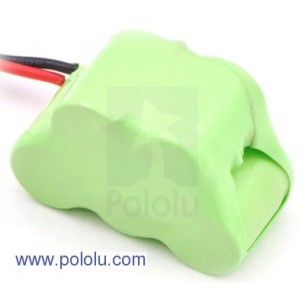
Pakiet NiMH składający się z 7 ogniw NiMH AAA o sumarycznym napięciu 8,4 V oraz pojemności 900 mAh. Konfiguracja ogniw 4+3. Posiada konektror JR, 3-pin żeński, wymiary: 46 x41 x 20mm, waga: 87,88g. Pololu 2236
Brak towaru
ACS715 Current Sensor Carrier 0 to 30A
Brak towaru
ACS711 Current Sensor Carrier -12.5 to +12.5A
Brak towaru
ACS711 Current Sensor Carrier -25 to +25A
Brak towaru
ACS709 Current Sensor Carrier -75 to +75A
Brak towaru
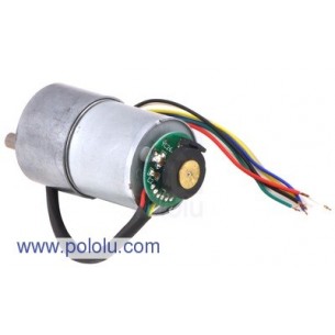
50:1 Metal Gearmotor 37Dx54L mm with 64 CPR Encoder
Brak towaru
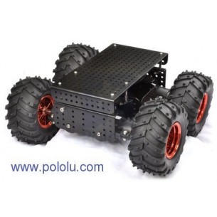
Terenowe podwozie Dagu Wild Thumper 4WD w kolorze czarnym, w komplecie koła o średnicy 120mm oraz silniki z przekładnią 75:1. Podwozie jest wykonane z blachy aluminiowej, otwory o średnicy 4mm rozmieszczone co 10mm umożliwiają montaż kontrolera oraz akcesoriów. Pololu 1567
Brak towaru
Brak towaru
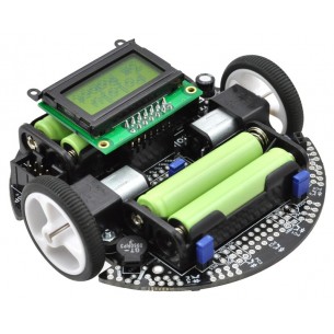
Platforma mobilna Line Follower z dwoma silnikami, 5-cioma czujnikami odbiciowymi, wyświetlaczem LCD, brzęczykiem i trzema przyciskami użytkownika. Oparty na mikrokontrolerze AVR ATmega328 programowanym w języku C. Pololu 975
Brak towaru
ACS715 Current Sensor Carrier 0 to 30A