


- Obecnie brak na stanie


ACS709 Current Sensor Carrier -75 to +75A
ACS709 Current Sensor Carrier -75 to +75A
This board is a simple carrier of Allegro’s ±75A ACS709 Hall effect-based linear current sensor with overcurrent fault output, which offers a low-resistance (~1.1 m?) current path and electrical isolation up to 2.1 kV RMS. The sensor has optimized accuracy for currents from -37.5 to 37.5 A, and the analog voltage output is linear for current magnitudes up to 75 A. The ratiometric output voltage is centered at VCC/2 and has a typical error of ±2%. It operates from 3 to 5.5 V, so it can interface directly to both 3.3 V and 5 V systems.
 |
This current sensor is a carrier board or breakout board for Allegro’s ACS709LLFTR-35BB-T Hall effect-based linear current sensor with overcurrent fault output; we therefore recommend careful reading of the ACS709 datasheet (483k pdf) before using this product. The sensor has an operating voltage of 3 – 5.5 V and an output sensitivity of 18.5 mV/A when Vcc is 3.3 V (or 28 mV/A when Vcc is 5 V). The following list details some of the sensor’s key features:
The pads are labeled on the bottom silkscreen, as shown in the picture above. The silkscreen also shows the direction that is interpreted as positive current flow via the +i arrow.
Note: The sensor’s extended -75 to 75 A range should be limited to transient currents. In our tests, we found that the IC could tolerate 50 A for 20 seconds or 37.5 A for 150 seconds before exceeding its maximum temperature rating of 150°C. Therefore, unless you are taking special steps to keep the IC cool, we recommend limiting continuous currents to under 30 A. Even with a low conductive path resistance of 1.1 mΩ, the board can get hot enough to burn you when the current is in the tens of amps, and the IC does not feature any kind of over-temperature protection, so thermal issues should be taken into consideration for high currents.
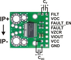 |
The only connections required to use this sensor are the input current (IP+ and IP-), logic power (VCC and GND), and the sensor output (VIOUT). All of the other pins are optional, as are the two external capacitors shown in the diagram to the right.
The sensor requires a supply voltage of 3 – 5.5 V to be connected across the VCC and GND pads, which are labeled on the bottom silkscreen. The sensor outputs an analog voltage that is linearly proportional to the input current. The quiescent output voltage is VCC/2 and changes by 28 mV per amp of input current (when VCC = 5 V), with positive current increasing the output voltage and negative current decreasing the output voltage. For an arbitrary input current i (in amps), the sensor’s output voltage can be more generally represented as:
VIOUT = (0.028 V/A * i + 2.5 V) * VCC / 5 V
The VZCR pin is the voltage reference output pin and can be used as a zero current (0 A) reference. It will be approximately equal to VCC/2 and lets you more accurately compute the current from the VIOUT output voltage.
The FILT pin lets you adjust the board’s bandwidth by adding a capacitor, CF, to ground (a ground pad has been added next to the FILT pin for convenience). Without any external filter capacitor, the bandwidth is 120 kHz. The datasheet provides more information on how the external filter capacitor affects bandwidth.
The FAULT pin is normally high and latches low when the current exceeds the overcurrent fault switchpoint (Ioc). This switchpoint is set by the voltage applied to the VOC pin and is dependent on the voltage divider shown in the schematic diagram below. By default, Ioc is set to 57 A, but it can be altered by adding external resistors to the voltage divider to change the VOC voltage. Once the FAULT pin is latched low, it can be reset by driving the FAULT_EN input low (this input is pulled high on the board). An external capacitor, COC, can be added to increase the overcurrent fault response time. Without this capacitor, the fault response time is typically under 2 us. For detailed information on using the overcurrent fault feature, including some key restrictions on the overcurrent threshold, please refer to the ACS709 datasheet (483k pdf).
|
|
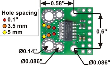
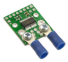
The input current can be connected to the board in a variety of ways. Holes with 0.1?, 3.5 mm, and 5 mm spacing are available as shown in the diagram above for connecting male header pins or terminal blocks. For high-current applications, you can solder wires directly to the through-holes that best match your wires, or you can use solderless ring terminal connectors, as shown in the picture above. The large through-holes are big enough for #6 screws.
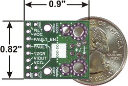
The board has two mounting holes on the logic side of the board. These mounting holes are 0.6" apart and are designed for #2 screws.
This board ships assembled with all surface mount components, and an 8?1 strip of 0.1? header pins is included but not soldered in, as shown in the picture below.
 |
| ACS709 current sensor carrier with included 8 ? 1 0.1? header pins. |
|---|
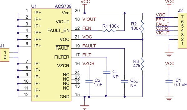 |
| ACS709 current sensor carrier schematic diagram. |
|---|
 |
ACS711 Current Sensor Carrier -12.5 to +12.5A |
 |
ACS714 Current Sensor Carrier -30 to +30A |
|
ACS711 Current Sensor Carrier -25 to +25A |
Cechy
Producent BTC Korporacja sp. z o. o. Lwowska 5 05-120 Legionowo Polska sprzedaz@kamami.pl 22 767 36 20
Osoba odpowiedzialna BTC Korporacja sp. z o. o. Lwowska 5 05-120 Legionowo Polska sprzedaz@kamami.pl 22 767 36 20
Brak towaru
Brak towaru
Brak towaru
Brak towaru
Brak towaru
Brak towaru
Brak towaru
Brak towaru
Brak towaru
Brak towaru
Brak towaru
Brak towaru
Brak towaru
Brak towaru
Brak towaru
Brak towaru
ACS709 Current Sensor Carrier -75 to +75A