


865,48 zł Netto
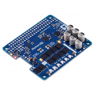
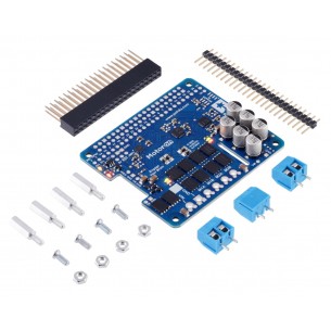
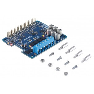
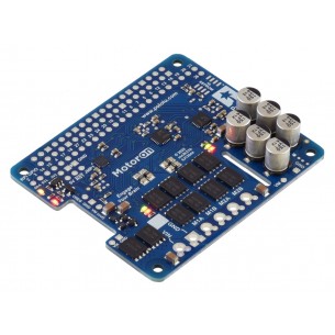
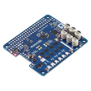
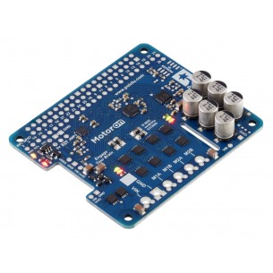
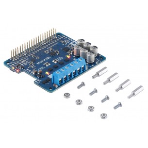
Dual VNH2SP30 Motor Driver Carrier MD03A umożliwia wydajne i bezpieczne sterowanie dwoma silnikami DC w robotach mobilnych oraz układach napędowych. Moduł sprawdza się w projektach wymagających dużej mocy, niezależnej kontroli silników i wysokiej odporności na przeciążenia. Pololu 708
Pololu 708 – Dual VNH2SP30 Motor Driver Carrier MD03A przeznaczony do sterowania dwoma silnikami prądu stałego w projektach robotycznych i mechatronicznych wymagających obsługi podwyższonych prądów. Moduł oparty na dwóch mostkach H VNH2SP30 umożliwia niezależną regulację prędkości i kierunku obrotów każdego silnika, co pozwala na realizację napędu różnicowego w platformach mobilnych.
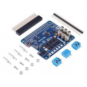
Sterownik współpracuje z mikrokontrolerami poprzez sygnały logiczne oraz sterowanie PWM, zapewniając płynną regulację pracy silników. Zintegrowane zabezpieczenia chronią układ przed przegrzaniem, przeciążeniem oraz zwarciem, zwiększając niezawodność w zastosowaniach prototypowych i eksploatacyjnych. Konstrukcja nośna ułatwia integrację z systemami zasilania i elementami wykonawczymi w robotach oraz pojazdach autonomicznych.
Cechy
Producent BTC Korporacja sp. z o. o. Lwowska 5 05-120 Legionowo Polska sprzedaz@kamami.pl 22 767 36 20
Osoba odpowiedzialna BTC Korporacja sp. z o. o. Lwowska 5 05-120 Legionowo Polska sprzedaz@kamami.pl 22 767 36 20
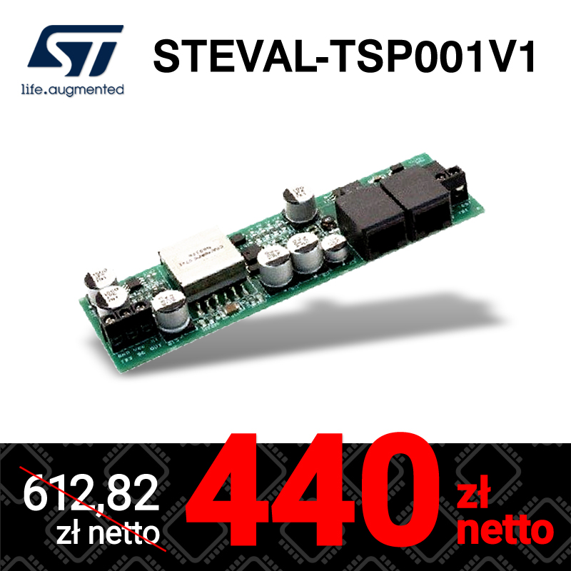
Automotive fully integrated H-bridge motor driver, MultiPowerSO-30, STM, RoHS
Brak towaru
Sterownik silników DC, który pozwala na kontrolowanie ruchu dwóch napędów za pomocą interfejsu I2C. Płytka bez złączy. Pololu 5059
Brak towaru
Sterownik silników DC, który pozwala na kontrolowanie ruchu dwóch napędów za pomocą interfejsu I2C. Złącza do montażu. Pololu 5058
Brak towaru
Sterownik silników DC, który pozwala na kontrolowanie ruchu dwóch napędów za pomocą interfejsu I2C. Płytka z przylutowanymi złączami. Pololu 5057
Brak towaru
Sterownik silników DC, który pozwala na kontrolowanie ruchu dwóch napędów za pomocą interfejsu I2C. Płytka bez złączy. Pololu 5056
Brak towaru
Sterownik silników DC, który pozwala na kontrolowanie ruchu dwóch napędów za pomocą interfejsu I2C. Płytka ze złączami do montażu. Pololu 5055
Brak towaru
Sterownik silników DC, który pozwala na kontrolowanie ruchu dwóch napędów za pomocą interfejsu I2C. Płytka z przylutowanymi złączami. Pololu 5054
Brak towaru
Sterownik silników DC, który pozwala na kontrolowanie ruchu dwóch napędów za pomocą interfejsu I2C. Płytka bez złączy. Pololu 5053
Brak towaru
Sterownik silników DC, który pozwala na kontrolowanie ruchu dwóch napędów za pomocą interfejsu I2C. Płytka ze złączami do montażu. Pololu 5052
Brak towaru
Sterownik silników DC, który pozwala na kontrolowanie ruchu dwóch napędów za pomocą interfejsu I2C. Płytka z przylutowanymi złączami. Pololu 5051
Brak towaru
Sterownik silników DC, który pozwala na kontrolowanie ruchu dwóch napędów za pomocą interfejsu I2C. Płytka bez złączy. Pololu 5050
Brak towaru
Sterownik silników DC, który pozwala na kontrolowanie ruchu dwóch napędów za pomocą interfejsu I2C. Płytka ze złączami do montażu. Pololu 5049
Brak towaru
Sterownik silników DC, który pozwala na kontrolowanie ruchu dwóch napędów za pomocą interfejsu I2C. Płytka z przylutowanymi złączami. Pololu 5048
Brak towaru
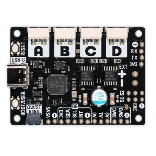
Moduł 4-kanałowego sterownika silników DC z mikrokontrolerem RP2040. Pozwala na podłączenie enkoderów i jest wyposażony w złącze QW/ST. Pimoroni PIM636
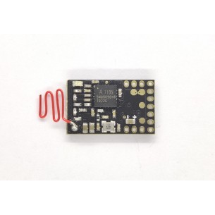
Moduł sterownika RC typu ESC z trainsceiverem A7105 umożliwiającym bezprzewodową komunikację danych pomiędzy urządzeniami elektronicznymi na niewielkie odległości przy niskim poborze energii. Pozwala na sterowanie dwoma silnikami w dwóch kierunkach oraz jednym silnikiem w jednym kierunku. Dasmigro 2.4G 7CH. Z
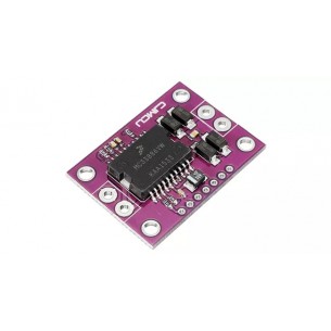
Moduł ze sterownikiem silników prądu stałego oparty na układzie MC33886. Pozwala na kontrolowanie ruchu napędów o napięciu pracy od 5 do 28 V i prądzie do 5 A
Brak towaru
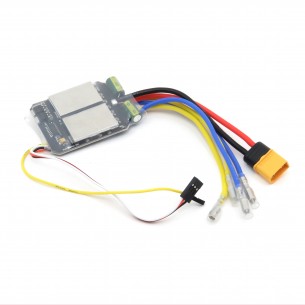
Dwukanałowy sterownik ESC do silników szczotkowych. Może dostarczyć prąd o natężeniu 40 A i ma przewody zakończone złączem XT60
Dual VNH2SP30 Motor Driver Carrier MD03A umożliwia wydajne i bezpieczne sterowanie dwoma silnikami DC w robotach mobilnych oraz układach napędowych. Moduł sprawdza się w projektach wymagających dużej mocy, niezależnej kontroli silników i wysokiej odporności na przeciążenia. Pololu 708