


145,93 zł Netto
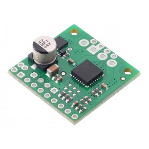
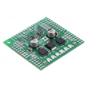
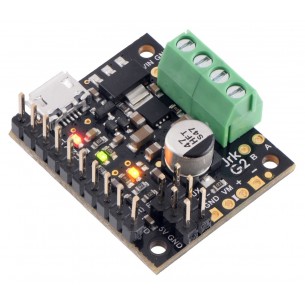
Wysokoprądowy sterownik silnika DC 24v12 umożliwia sterowanie silnikiem DC w systemach do 40 V przy zachowaniu kompaktowych wymiarów i prostego interfejsu PWM/DIR. Moduł sprawdza się w napędach robotów i urządzeń mobilnych wymagających prądu do 12 A bez radiatora, przy możliwości zwiększenia wydajności prądowej przez dodatkowe chłodzenie i odpowiednie filtrowanie zasilania. Pololu 757
Pololu High-Power Motor Driver 24v12 przeznaczony do dwukierunkowego sterowania jednym szczotkowym silnikiem prądu stałego o podwyższonej mocy. Moduł wykorzystuje dyskretny mostek H oparty na tranzystorach MOSFET typu N i obsługuje napięcie zasilania w zakresie 5,5–40 V. Kompaktowa płytka o wymiarach 1,3 × 0,8 cala umożliwia dostarczanie do 12 A prądu ciągłego bez radiatora, a przy dodatkowym chłodzeniu do około 17 A.
Sterownik oferuje prosty interfejs sterowania wymagający dwóch linii sygnałowych, co ułatwia integrację z mikrokontrolerami i sterownikami nadrzędnymi. Obsługa trybów sign-magnitude oraz locked-antiphase umożliwia dobór sposobu regulacji prędkości i kierunku do wymagań aplikacji. Zintegrowana detekcja wybranych zwarć oraz sygnalizacja stanów awaryjnych na wyjściach FF1 i FF2 zwiększają odporność na typowe błędy okablowania.
Układ nie posiada sprzętowej ochrony przed odwrotną polaryzacją ani zabezpieczeń nadprądowych i temperaturowych, dlatego w aplikacjach pracujących blisko granic parametrów zalecane jest stosowanie odpowiednio dobranej pojemności filtrującej przy zasilaniu, zapewnienie chłodzenia oraz monitorowanie prądu z wykorzystaniem zewnętrznego czujnika.
Cechy
Producent BTC Korporacja sp. z o. o. Lwowska 5 05-120 Legionowo Polska sprzedaz@kamami.pl 22 767 36 20
Osoba odpowiedzialna BTC Korporacja sp. z o. o. Lwowska 5 05-120 Legionowo Polska sprzedaz@kamami.pl 22 767 36 20
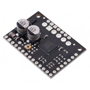
TB9051FTG Single Brushed DC Motor Driver Carrier to pojedynczy sterownik silników DC, który umożliwia zasilanie silnika napięciem w zakresie 4,5...28V i poborze prądu przy pracy ciągłej 2,6A (5A w szczycie). Pololu 2997
Moduł sterownika silników DC z dwoma kanałami, dedykowany do stosowania w modelarstwie. Może być sterowany za pomocą nadajnika RC i wykorzystuje sygnał PPM. DFRobot DFR0513
Moduł sterownika silnika krokowego TB67S279FTG zasilanego napięciem 10-47V i prądzie pracy 1,2A. Sterownik pozwala na kontrolowanie ruchu silnika aż z 7 różnymi rozdzielczościami (do 1/32 kroku). Pololu 2974
Moduł sterownika silnika krokowego TB67S249FTG zasilanego napięciem 10-47V i prądzie pracy 1,7A. Sterownik pozwala na kontrolowanie ruchu silnika aż z 7 różnymi rozdzielczościami (do 1/32 kroku). Pololu 2973
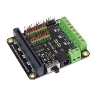
Moduł rozszerzeń przeznaczony do współpracy z micro:bit. Pozwala na sterownie 4 silnikami DC lub dwoma silnikami krokowymi i 8 serwami. Komunikuje się przez interfejs I2C. DFRobot DFR0548
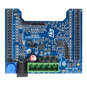
X-NUCLEO-IHM16M1 to płytka rozszerzeń ze sterownikiem trójfazowego bezszczotkowego silnika zasilanym napięciem w zakresie 7-45 V o maksymalnym prądzie wyjściowym 1,5 A w każdym z kanałów. Kompatybilny z STM32 Nucleo. X-NUCLEO-IHM16M1
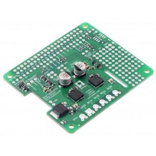
Podwójny sterownik silników DC przeznaczony dla Arduino, który umożliwia zasilanie silnika napięciem w zakresie 4,5-28V i poborze prądu przy pracy ciągłej 2,6A (5A w szczycie) dwóch silników DC. Pololu 2520
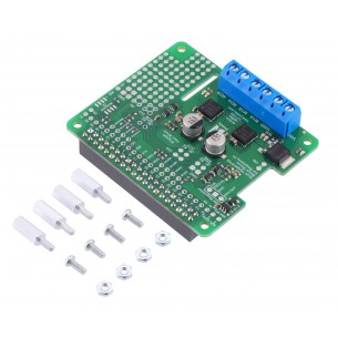
Podwójny sterownik silników DC przeznaczony dla Raspberry Pi, który umożliwia zasilanie silnika napięciem w zakresie 4,5-28V i poborze prądu przy pracy ciągłej 2,6A (5A w szczycie) dwóch silników DC. Pololu 2762
Podwójny sterownik silników DC przeznaczony dla Raspberry Pi, który umożliwia zasilanie silnika napięciem w zakresie 4,5-28V i poborze prądu przy pracy ciągłej 2,6A (5A w szczycie) dwóch silników DC. Zestaw do samodzielnego montażu. Pololu 2761
Sterownik silnika prądu stałego (DC) o napięciu pracy 4,5..28V i maksymalnym prądzie ciągłym 2,6A. Posiada możliwość łatwej realizacji pętli sprzężenia zwrotnego oraz liczne interfejsy sterujące. Pololu 3143
Brak towaru
Sterownik silnika prądu stałego (DC) o napięciu pracy 4,5-28V i maksymalnym prądzie ciągłym 2,6A. Posiada możliwość łatwej realizacji pętli sprzężenia zwrotnego oraz liczne interfejsy sterujące. Pololu 3142
Brak towaru
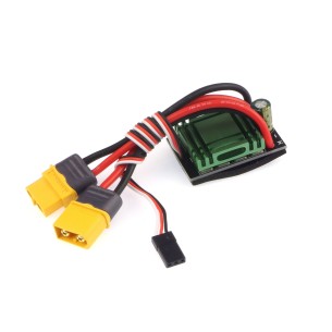
Dwukierunkowy kontroler prędkości ESC do silników szczotkowych. Może dostarczyć prąd o natężeniu 20 A i ma przewody zakończone złączem XT60. DFRobot DRI0047
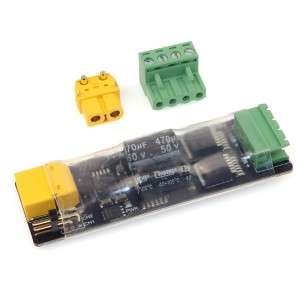
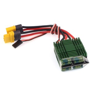
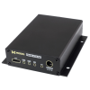
Dwukierunkowy kontroler prędkości (ESC) bez hamulca to zaawansowane urządzenie do sterowania silnikami szczotkowymi, oferujące prąd ciągły do 40 A i chwilowy do 340 A, co zapewnia stabilne działanie i dynamiczną reakcję na obciążenie. Sterowanie sygnałem PPM umożliwia precyzyjną kontrolę prędkości i kierunku obrotów silnika, a radiator i złącze XT60 gwarantują bezpieczne użytkowanie i skuteczne chłodzenie.
Brak towaru
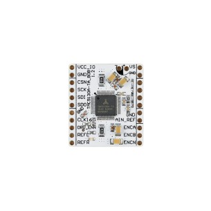
TMC5130A-BOB umożliwia wygodne testowanie i integrację sterowania silnikami krokowymi w aplikacjach wymagających precyzyjnego pozycjonowania i kontroli ruchu. Zintegrowane funkcje rampowania, interpolacji mikrokroków i enkodera czynią ją idealnym wyborem do zastosowań w automatyce, robotyce i systemach mechatronicznych.
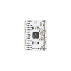
TMC5072-BOB to kompaktowa płytka wyprowadzeniowa z układem TMC5072, przeznaczona do szybkiego prototypowania rozwiązań z precyzyjnym sterowaniem ruchem. Wysoka rozdzielczość mikrokrokowa, wsparcie dla enkoderów oraz szeroki zakres napięcia zasilania czynią ją odpowiednim wyborem do projektów takich jak drukarki 3D, sterowniki osi CNC czy manipulatory robotyczne. TMC5072-BOB
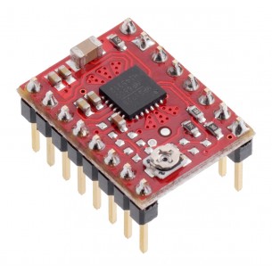
Sterownik silnika krokowego z układem MP6500 z potencjometrem do regulacji prądu. Pozwala na zasilanie silnika bipolarnego prądem do 1,5A na fazę bez użycia radiatora. Pololu 2967
Brak towaru
Wysokoprądowy sterownik silnika DC 24v12 umożliwia sterowanie silnikiem DC w systemach do 40 V przy zachowaniu kompaktowych wymiarów i prostego interfejsu PWM/DIR. Moduł sprawdza się w napędach robotów i urządzeń mobilnych wymagających prądu do 12 A bez radiatora, przy możliwości zwiększenia wydajności prądowej przez dodatkowe chłodzenie i odpowiednie filtrowanie zasilania. Pololu 757