Produkty
Kategorie
- Kategorie główne
-
- ARDUINO
- AUTOMATYKA
- CYBERBEZPIECZEŃSTWO
- DRUK 3D
- EDUKACJA
- ELEKTRONIKA
- Akcesoria PC
- Chłodzenie
- Czujniki
- Czujniki 6DOF/9DOF/10DOF
- Czujniki ciśnienia
- Czujniki gazów
- Czujniki Halla
- Czujniki jakości cieczy
- Czujniki jakości powietrza
- Czujniki magnetyczne (kompasy)
- Czujniki medyczne
- Czujniki nacisku
- Czujniki odbiciowe
- Czujniki odległości
- Czujniki PH
- Czujniki podczerwieni
- Czujniki poziomu cieczy
- Czujniki położenia
- Czujniki prądu
- Czujniki przepływu
- Czujniki przyspieszenia (akcelerometry)
- Czujniki ruchu
- Czujniki światła i koloru
- Czujniki temperatury
- Czujniki wibracji
- Czujniki wilgotności gleby
- Czujniki wilgotności powietrza
- Żyroskopy
- Drukarki
- Elementy pasywne
- Gadżety
- GPS
- Inteligentne ubrania
- Kamery i akcesoria
- Karty pamięci i inne nośniki danych
- Komunikacja
- LED - diody, wyświetlacze, paski
- Materiały przewodzące
- Moduły elektroniczne
- Akcesoria JTAG
- Audio
- Czytniki kart pamięci
- Czytniki kodów paskowych
- Czytniki linii papilarnych
- Ekspandery linii I/O
- Enkodery
- Generatory DDS/PLL
- Klawiatury, przyciski
- Konwertery CAN
- Konwertery napięć
- Konwertery RS485
- Konwertery USB - I2C / 1-Wire / SPI
- Konwertery USB - UART / RS232
- Moduły HMI
- Moduły pamięci
- Moduły RTC
- Moduły z wyjściami mocy
- Moduły zasilające
- Obraz i wideo
- Odbiorniki podczerwieni TSOP
- Potencjometry cyfrowe
- Przetworniki A/C i C/A
- Rejestratory danych (data logger)
- Sterowniki LED
- Sterowniki serw
- Sterowniki silników
- Półprzewodniki
- Button
- Czujniki
- Czujniki dotykowe (Touch)
- Diody
- Energy harvesting
- Generatory PLL
- Inne
- Konwertery logiczne
- Liczniki energii
- Mikrokontrolery
- Mikroprocesory DSP
- Mostki prostownicze
- Optotriaki i transoptory
- Pamięci
- Przetworniki a/c (ADC)
- Przetworniki c/a (DAC)
- Sterowniki i mostki IGBT
- Sterowniki LED
- Sterowniki silników
- Syntezery DDS
- Timery
- Tranzystory
- Układy analogowe
- Układy audio
- Układy cyfrowe
- Układy interfejsowe
- Układy programowalne
- Układy RF
- Układy RTC
- Układy SoC
- Układy zasilające
- Układy zerujące
- Zabezpieczenia ESD
- Przekaźniki
- Przetworniki dźwięku
- Przewody
- Przewody świecące i akcesoria
- Przełączniki i przyciski
- Płytki prototypowe
- Wizja maszynowa (MV)
- Wyświetlacze
- Złącza
- Adaptery USB PD do laptopów
- Gniazda do kart pamięci
- Igły testowe (pogo pin)
- Konektory
- Podstawki
- Szybkozłącza
- Zworki
- Złącza ARK (Terminal Block)
- Złącza FFC / FPC ZIF
- Złącza goldpin
- Złącza IDC
- Złącza inne
- Złącza Jack
- Złącza JST
- Złącza koncentryczne (RF)
- Złącza krokodylkowe
- Złącza obrotowe
- Złącza RJ-45
- Złącza szufladowe D-Sub
- Złącza USB
- Złącza zasilania DC
- Akcesoria PC
- KSIĄŻKI
- MECHANIKA
- MINIKOMPUTERY (SBC)
- PRZYRZĄDY POMIAROWE
- RASPBERRY PI
- Akcesoria do Raspberry Pi
- Chłodzenie do Raspberry Pi
- Kamery do Raspberry Pi
- Karty pamięci do Raspberry Pi
- Moduły rozszerzające do Raspberry Pi
- Obudowy do Raspberry Pi
- Prototypowanie Raspberry Pi
- Przewody audio-wideo do Raspberry Pi
- Raspberry Pi 3 model A+
- Raspberry Pi 3 model B
- Raspberry Pi 3 model B+
- Raspberry Pi 4 model B
- Raspberry Pi 400
- Raspberry Pi 5
- Raspberry Pi 500
- Raspberry Pi Compute Module
- Raspberry Pi model A/B+/2
- Raspberry Pi Pico
- Raspberry Pi Zero
- Raspberry Pi Zero 2 W
- Wyświetlacze do Raspberry Pi
- Zasilanie do Raspberry Pi
- WARSZTAT
- Chemia
- Elektronarzędzia
- Igły dozownicze
- Imadła
- Kleje i klejarki
- Listwy zasilające
- Lutowanie
- Akcesoria do lutowania
- Akcesoria SMD
- Chemia lutownicza
- Cyna
- Gąbki i czyściki
- Groty do lutownic
- Grzałki oraz kolby lutownicze
- Kulki BGA
- Laminaty
- Lutownice kolbowe
- Lutownice przenośne
- Maty i akcesoria antystatyczne (ESD)
- Myjki ultradźwiękowe
- Odsysacze do usuwania cyny
- Opalarki
- Pasty lutownicze
- Pędzle i szczotki ESD
- Plecionki do usuwania cyny
- Podgrzewacze
- Podstawki pod lutownice
- Silikonowe maty do lutowania
- Stacje lutownicze
- Tygle lutownicze
- Uchwyty, lupy
- Mikroskopy
- Miniwiertarki, miniszlifierki
- Narzędzia
- Noże i nożyczki
- Okulary ochronne
- Organizery
- Pęsety
- Plotery i Frezarki CNC
- Rurki termokurczliwe
- Ściągacze izolacji
- Taśmy
- Zaciskarki
- Zasilacze laboratoryjne
- Chemia
- WYCOFANE Z OFERTY
- WYPRZEDAŻ
- ZASILANIE
- ZESTAWY URUCHOMIENIOWE
- Atmel SAM
- Atmel Xplain
- AVR
- DFRobot FireBeetle
- ESP32
- ESP8266
- Feather / Thing Plus
- Freedom (Kinetis)
- Google Coral
- Inne zestawy uruchomieniowe
- M5Stack
- micro:bit
- Moduły peryferyjne
- Nordic nRF
- OPROGRAMOWANIE
- Particle Photon
- PIC
- Programatory Segger
- Programatory uniwersalne
- Raspberry Pi RP2040
- RFID
- RISC-V
- Seeed Studio LinkIt
- Sparkfun MicroMod
- STM32
- STM32 Discovery
- STM32 MP1
- STM32 Nucleo
- STM8
- Teensy
- WRTNode
- XIAO/Qt PY
- Atmel SAM
- ZESTAWY URUCHOMIENIOWE FPGA
- ARDUINO
Nowości
Nowości
31,77 zł Netto
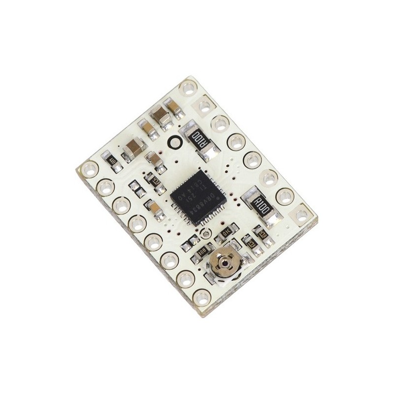
DRV8834 Low-Voltage Stepper Motor Driver Carrier
Wysyłka gratis
darmowa wysyłka na terenie Polski dla wszystkich zamówień powyżej 500 PLN
Wysyłka tego samego dnia
Jeśli Twoja wpłata zostanie zaksięgowana na naszym koncie do godz. 11:00
14 dni na zwrot
Każdy konsument może zwrócić zakupiony towar w ciągu 14 dni bez zbędnych pytań
DRV8834 Low-Voltage Stepper Motor Driver Carrier
This product is a carrier board or breakout board for TI’s DRV8834 low-voltage stepper motor driver; we therefore recommend careful reading of the DRV8834 datasheet (2MB pdf) before using this product. This stepper motor driver lets you control one bipolar stepper motor at up to 2 A output current per coil (see the Power Dissipation Considerations section below for more information). Here are some of the driver’s key features:
- Simple step and direction control interface
- Six different step resolutions: full-step, half-step, 1/4-step, 1/8-step, 1/16-step, and 1/32-step
- Adjustable current control lets you set the maximum current output with a potentiometer, which lets you use voltages above your stepper motor’s rated voltage to achieve higher step rates
- Intelligent chopping control that automatically selects the correct current decay mode (fast decay or slow decay)
- 2.5-10.8 V supply voltage range
- Built-in regulator (no external logic voltage supply needed)
- Can interface directly with 3.3 V and 5 V systems
- Over-temperature thermal shutdown, over-current shutdown, and under-voltage lockout
- Short-to-ground, short-to-supply, and shorted-load protection
- 4-layer, 2 oz copper PCB for improved heat dissipation
- Exposed solderable ground pad below the driver IC on the bottom of the PCB
- Module size, pinout, and interface match those of our A4988 stepper motor driver carriers in most respects (see the bottom of this page for more information)
This product ships with all surface-mount components—including the DRV8834 driver IC—installed as shown in the product picture.
For alternative, pin-compatible stepper motor drivers that work with higher motor supply voltages, consider our DRV8825 carrier, DRV8824 carrier, and A4988 carrier (also available in a Black Edition and a version with voltage regulators).
Some unipolar stepper motors (e.g. those with six or eight leads) can be controlled by this driver as bipolar stepper motors. For more information, please see the frequently asked questions. Unipolar motors with five leads cannot be used with this driver.
Included hardware
The DRV8834 stepper motor driver carrier ships with one 1×16-pin breakaway 0.1" male header. The headers can be soldered in for use with solderless breadboards or 0.1" female connectors. You can also solder your motor leads and other connections directly to the board.
|
|
Using the driver
Minimal wiring diagram for connecting a microcontroller to a DRV8834 stepper motor driver carrier (1/4-step mode). |
---|
Power connections
The driver requires a motor supply voltage of 2.5-10.8 V to be connected across VMOT and GND. This supply should have appropriate decoupling capacitors close to the board, and it should be capable of delivering the expected stepper motor current.
Warning: This carrier board uses low-ESR ceramic capacitors, which makes it susceptible to destructive LC voltage spikes, especially when using power leads longer than a few inches. Under the right conditions, these spikes can exceed the 11.8 V maximum voltage rating for the DRV8834 and permanently damage the board, even when the motor supply voltage is as low as 9 V. One way to protect the driver from such spikes is to put a large (at least 47 µF) electrolytic capacitor across motor power (VMOT) and ground somewhere close to the board.
Motor connections
Four, six, and eight-wire stepper motors can be driven by the DRV8834 if they are properly connected; a FAQ answer explains the proper wirings in detail.
Warning: Connecting or disconnecting a stepper motor while the driver is powered can destroy the driver. (More generally, rewiring anything while it is powered is asking for trouble.)
Step (and microstep) size
Stepper motors typically have a step size specification (e.g. 1.8° or 200 steps per revolution), which applies to full steps. A microstepping driver such as the DRV8834 allows higher resolutions by allowing intermediate step locations, which are achieved by energizing the coils with intermediate current levels. For instance, driving a motor in quarter-step mode will give the 200-step-per-revolution motor 800 microsteps per revolution by using four different current levels.
The resolution (step size) selector inputs (M0 and M1) enable selection from the six step resolutions according to the table below. M0 is floating by default, while M1 has an internal 200 k? pull-down resistor, so leaving these two microstep selection pins disconnected results in 1/4-step mode. For the microstep modes to function correctly, the current limit must be set low enough (see below) so that current limiting gets engaged. Otherwise, the intermediate current levels will not be correctly maintained, and the motor will skip microsteps.
M0 | M1 | Microstep Resolution |
---|---|---|
Low | Low | Full step |
High | Low | Half step |
Floating | Low | 1/4 step |
Low | High | 1/8 step |
High | High | 1/16 step |
Floating | High | 1/32 step |
Control inputs
Each pulse to the STEP input corresponds to one microstep of the stepper motor in the direction selected by the DIR pin. These inputs are both pulled low by default through internal 200 k? pull-down resistors. If you just want rotation in a single direction, you can leave DIR disconnected.
The chip has two different inputs for controlling its power states: SLEEP and ENBL. For details about these power states mode, see the datasheet. Please note that the driver pulls the SLEEP pin low through an internal 500 k? pull-down resistor, and it pulls the ENBL pin low through an internal 200 k? pull-down resistor. The default SLEEP state prevents the driver from operating; this pin must be high to enable the driver (it can be connected directly to a logic “high” voltage between 2.5 and 5.5 V, or it can be dynamically controlled by connecting it to a digital output of an MCU). The default state of the ENBL pin is to enable the driver, so this pin can be left disconnected.
Schematic of nSLEEP and nFAULT pins on DRV8824/DRV8825/DRV8834 carriers. |
---|
The DRV8834 also features a FAULT output that drives low whenever the H-bridge FETs are disabled as the result of over-current protection or thermal shutdown, or while the undervoltage lockout is disabling the chip. The carrier board connects this pin to the SLEEP pin through a 10k resistor that acts as a FAULT pull-up whenever SLEEP is externally held high, so no external pull-up is necessary on the FAULT pin. Note that the carrier includes a 1.5k protection resistor in series with the FAULT pin that makes it is safe to connect this pin directly to a logic voltage supply, as might happen if you use this board in a system designed for the pin-compatible A4988 carrier. In such a system, the 10k resistor between SLEEP and FAULT would then act as a pull-up for SLEEP, making the DRV8834 carrier more of a direct replacement for the A4988 in such systems (the A4988 has an internal pull-up on its SLEEP pin). To keep faults from pulling down the SLEEP pin, any external pull-up resistor you add to the SLEEP pin input should not exceed 4.7k.
Optional pin jumpers
The CONFIG pin on the DRV8834 can be used to select between its default indexer mode, which is intended for controlling stepper motors, and an alternate phase/enable mode that can be used to drive two brushed DC motors. It is not made available by default (to avoid conflicts when using the DRV8834 carrier as a drop-in replacement for our other stepper motor driver carriers), but it can be connected to the pin labeled “(CFG)” by bridging the surface mount jumper indicated in the picture below. A second jumper can be bridged to make the current limit reference voltage available on the pin labeled “(REF)”.
Current limiting
To achieve high step rates, the motor supply is typically higher than would be permissible without active current limiting. For instance, a typical stepper motor might have a maximum current rating of 1 A with a 5 ? coil resistance, which would indicate a maximum motor supply of 5 V. Using such a motor with 9 V would allow higher step rates, but the current must actively be limited to under 1 A to prevent damage to the motor.
The DRV8834 supports such active current limiting, and the trimmer potentiometer on the board can be used to set the current limit. You will typically want to set the driver’s current limit to be at or below the current rating of your stepper motor. One way to set the current limit is to put the driver into full-step mode and to measure the current running through a single motor coil without clocking the STEP input. The measured current will be 0.7 times the current limit (since both coils are always on and limited to approximately 70% of the current limit setting in full-step mode).
Another way to set the current limit is to measure the voltage on the “ref” pin and to calculate the resulting current limit (the current sense resistors are 0.100 ?). The ref pin voltage is accessible on a via that is circled on the bottom silkscreen of the circuit board, or on the pin labeled “(REF)” if the appropriate surface mount jumper is connected (see above). The current limit relates to the reference voltage as follows:
Current Limit = VREF × 2
So, for example, if you have a stepper motor rated for 1 A, you can set the current limit to 1 A by setting the reference voltage to 0.5 V.
Note: The coil current can be very different from the power supply current, so you should not use the current measured at the power supply to set the current limit. The appropriate place to put your current meter is in series with one of your stepper motor coils.
Power dissipation considerations
The DRV8834 driver IC has a maximum continuous current rating of 1.5 A per coil, and in our tests, this carrier board was capable of supplying the rated current for many minutes without requiring additional cooling. The DRV8834 can support peak currents of up to 2.2 A per coil, but its overcurrent protection might kick in at currents as low as 2 A, and the actual current you can deliver depends on how well you can keep the IC cool. The carrier’s printed circuit board is designed to draw heat out of the IC, but to supply more than approximately 1.5 A per coil, a heat sink or other cooling method is required.
This product can get hot enough to burn you long before the chip overheats. Take care when handling this product and other components connected to it.
Please note that measuring the current draw at the power supply will generally not provide an accurate measure of the coil current. Since the input voltage to the driver can be significantly higher than the coil voltage, the measured current on the power supply can be quite a bit lower than the coil current (the driver and coil basically act like a switching step-down power supply). Also, if the supply voltage is very high compared to what the motor needs to achieve the set current, the duty cycle will be very low, which also leads to significant differences between average and RMS currents. Additionally, please note that the coil current is a function of the set current limit, but it does not necessarily equal the current limit setting. The actual current through each coil changes with each microstep. See the DRV8834 datasheet for more information.
Schematic diagram
Schematic diagram for the DRV8834 low-voltage stepper motor driver carrier. |
---|
This schematic is also available as a downloadable pdf (105k pdf).
Key differences between the DRV8834 and A4988
The DRV8834 carrier was designed to be as similar to our A4988 stepper motor driver carriers as possible, and it can be used as a drop-in replacement for the A4988 carrier in many applications because it shares the same size, pinout, and general control interface. There are a few differences between the two modules that should be noted, however:
DRV8834 low-voltage stepper motor driver carrier. |
---|
A4988 stepper motor driver carrier, Black Edition |
---|
- The pin used to supply logic voltage to the A4988 is used as the DRV8834’s FAULT output, since the DRV8834 does not require a logic supply (and the A4988 does not have a fault output). Note that it is safe to connect the FAULT pin directly to a logic supply (there is a 1.5k resistor between the IC output and the pin to protect it), so the DRV8834 module can be used in systems designed for the A4988 that route logic power to this pin.
- The SLEEP pin on the DRV8834 is not pulled up by default like it is on the A4988, but the carrier board does connect it to the FAULT pin through a 10k resistor. Therefore, systems intended for the A4988 that route logic power to the FAULT pin will effectively have a 10k pull-up on the SLEEP pin.
- The current limit potentiometer is in a different location.
- The relationship between the current limit setting and the reference pin voltage is different.
- The DRV8834 offers 1/32-step microstepping; the A4988 only goes down to 1/16-step.
- The DRV8834 only has two pins for setting its microstep mode; the A4988 has three. The step selection table differs between the DRV8834 and A4988 for all microstepping resolutions other than full-step and half-step mode. On the DRV8834, the M0 pin must be left in a floating (high-impedance) state to select some of the microstepping modes. The default microstepping mode on the DRV8834 is 1/4-step while the default microstepping mode on the A4988 is full-step.
- The DRV8834 has no RESET input.
- The pins on the DRV8834 carrier corresponding to the A4988 carrier’s MS3 and RESET pins are disconnected by default. If electrical compatibility with the A4988 carrier is not a concern, two different signals (CONFIG and VREF) on the DRV8834 carrier can be connected to these pins with surface mount jumpers (described in the “Optional pin jumpers” section above).
- The timing requirements for minimum pulse durations on the STEP pin are different for the two drivers. With the DRV8834, the high and low STEP pulses must each be at least 1.9 us; they can be as short as 1 us when using the A4988.
- The DRV8834 supports lower supply voltages than the A4988, but its maximum supply voltage is also lower (2.5–10.8 V vs 8–35 V).
- The DRV8834 can deliver more current than the A4988 without any additional cooling (based on our full-step tests: 1.5 A per coil for the DRV8834 vs 1.2 A per coil for the A4988 Black Edition and 1 A per coil for the original A4988 carrier).
- The DRV8834 uses a different naming convention for the stepper motor outputs, but they are functionally the same as the corresponding pins on the A4988 carrier, so the same connections to both drivers result in the same stepper motor behavior. On both boards, the first part of the label identifies the coil (so you have coils “A” and “B” on the DRV8834 and coils “1” and “2” on the A4988).
- For those with color-sensitive applications, note that the DRV8834 carrier is white.
In summary, the DRV8834 carrier is similar enough to our A4988 carriers that the minimum connection diagram for the A4988 is a valid alternate way to connect the DRV8834 to a microcontroller as well:
Alternative minimal wiring diagram for connecting a microcontroller to a DRV8834 stepper motor driver carrier (1/4-step mode). |
---|
Cechy
- Prąd wyjściowy
- 2 A
- Ilość kanałów
- 2
- Napięcie zasilania od
- 2,5 V
- Napięcie zasilania do
- 10,8 V
Osoba odpowiedzialna BTC Korporacja sp. z o. o. Lwowska 5 05-120 Legionowo Polska sprzedaz@kamami.pl 22 767 36 20
Produkty z tej samej kategorii (16)
Moduł sterownika ESC do silnika bezszczotkowego o wydajności prądowej do 120 A. Może współpracować z pakietami LiPo od 5S do 12S. Wykorzystuje oprogramowanie BLHeli_32. FLYCOLOR X-CROSS HV
Pololu G2 24v19 High Power to miniaturowy sterownik silnika DC. Zasilanie sterownika: 6,5...40V. Wydajność prądowa modułu: 19A. Moduł posiada zabezpieczenie przed napięciem wstecznym i przepięciami. Pololu 1367
Brak towaru
Podwójny sterownik silników pozwalający na sterowanie dwóch silników DC napięciem 2,7-10,8V i prądem ciągłym 1,2A na kanał. Pololu 2130
Brak towaru
Zestaw z regulatorem prędkości ESC ODrive3.6 oraz silnikiem BLDC MKS X2212. Sterownik przeznaczony jest do zasilania dwóch trójfazowych silników bezszczotkowych w różnych aplikacjach, takich jak roboty jeżdżące, roboty kroczące czy gimbale. Obsługuje zakres napięcia wejściowego od 12 V do 56 V oraz maksymalny prąd do 60 A. Makerbase ODrive3.6 Kit
Brak towaru
Dual VNH3SP30 Motor Driver Carrier MD03A
Dwukanałowy sterownik silników DC - 2 x 7 A. Maksymalny prąd chwilowy 50 A. Zasilanie od 7 do 24 V. Sterowany sygnałem PWM. DFRobot DRI0041
Brak towaru
Sterownik silników DC, który pozwala na kontrolowanie ruchu dwóch napędów za pomocą interfejsu I2C. Płytka bez złączy. Pololu 5044
Brak towaru
Moduł ze sterownikiem bipolarnego silnika krokowego TMC2209. Umożliwia sterowanie z napięciem zasilania z zakresu od 4,75 do 29 V oraz prądem do 2,8 A
Sterownik silnika krokowego, napięcie zasilania cewek silnika 6..30 V, napięcie pracy logiki sterownika 0..5 V lub 0..3,3 V. Możliwa regulacja prądu sterowania na fazę obrotu podczas pracy sterownika. ROB-12779
X-NUCLEO-IHM11M1 to niskonapięciowy sterownik trójfazowych silników bezszczotkowych DC (BLDC) dla płytek serii STM32 Nucleo. Shield oparty jest na układzie STSPIN230. Idealnie nadaje się do użycia w urządzeniach zasilanych z baterii (roboty, zabawki). Shield wyposażony jest w złącze zgodne ze standardem Arduino UNO R3
RoboClaw 2x7A Motor Controller (V5B) to dwukanałowy sterownik silników prądu stałego (DC), napięcie pracy: 6-34 V, maksymalny prąd ciągły: 7,5 A, możliwość łatwej realizacji pętli sprzężenia zwrotnego z regulatorem PID, systemy bezpieczeństwa. Pololu 3284
Sterownik silników używający Serial portu do komunikacji z mikrokontrolerem. Sparkfun ROB-09571
Jednokanałowy sterownik silników DC z interfejsem UART TTL. Jest zasilany napięciem od 1,8 V do 22 V i może dostarczyć prąd o natężeniu do 1,8 A. Płytka z przylutowanymi złączami. Pololu 5076
Sterownik silnika prądu stałego (DC) o napięciu pracy 6,5-40V i maksymalnym prądzie ciągłym 13A. Posiada możliwość łatwej realizacji pętli sprzężenia zwrotnego oraz liczne interfejsy sterujące. Pololu 3147
A4988 Stepper Motor Driver Carrier with Voltage Regulators
Dwukanałowy sterownik silników DC z interfejsem I2C. Jest zasilany napięciem od 1,8 V do 22 V i może dostarczyć prąd o natężeniu do 1,6 A na silnik. Płytka ze złączami do montażu. Pololu 5079