


29,30 zł Netto
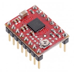
A4988 Stepper Motor Driver Carrier with Voltage Regulators umożliwia precyzyjne sterowanie silnikami krokowymi z wykorzystaniem mikrokroku i regulacji prądu. Moduł sprawdza się w aplikacjach wymagających dokładnego pozycjonowania oraz prostej integracji z popularnymi mikrokontrolerami. Pololu 1183
Pololu 1183 – A4988 Stepper Motor Driver Carrier with Voltage Regulators przeznaczony do sterowania bipolarnymi silnikami krokowymi w projektach robotycznych, automatyce oraz systemach precyzyjnego pozycjonowania. Moduł oparty na układzie A4988 umożliwia realizację mikrokroku, co pozwala na płynniejszy ruch silnika, zmniejszenie drgań oraz poprawę dokładności pozycjonowania.
Zintegrowane stabilizatory napięcia umożliwiają bezpośrednie zasilanie części logicznej z wyższego napięcia, upraszczając integrację z mikrokontrolerami pracującymi z logiką 3,3 V lub 5 V. Regulowany ogranicznik prądu pozwala na dopasowanie parametrów pracy do konkretnego silnika, chroniąc go przed przeciążeniem. Moduł znajduje zastosowanie w drukarkach 3D, ploterach, frezarkach CNC, manipulatorach oraz projektach edukacyjnych.
Cechy
Producent BTC Korporacja sp. z o. o. Lwowska 5 05-120 Legionowo Polska sprzedaz@kamami.pl 22 767 36 20
Osoba odpowiedzialna BTC Korporacja sp. z o. o. Lwowska 5 05-120 Legionowo Polska sprzedaz@kamami.pl 22 767 36 20
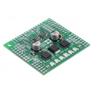
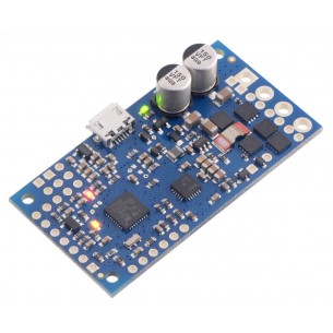
Podwójny sterownik silników DC przeznaczony dla Arduino, który umożliwia zasilanie silnika napięciem w zakresie 4,5-28V i poborze prądu przy pracy ciągłej 2,6A (5A w szczycie) dwóch silników DC. Pololu 2520
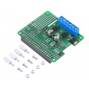
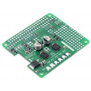
Podwójny sterownik silników DC przeznaczony dla Raspberry Pi, który umożliwia zasilanie silnika napięciem w zakresie 4,5-28V i poborze prądu przy pracy ciągłej 2,6A (5A w szczycie) dwóch silników DC. Pololu 2762
Podwójny sterownik silników DC przeznaczony dla Raspberry Pi, który umożliwia zasilanie silnika napięciem w zakresie 4,5-28V i poborze prądu przy pracy ciągłej 2,6A (5A w szczycie) dwóch silników DC. Zestaw do samodzielnego montażu. Pololu 2761
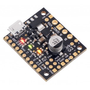
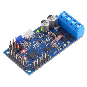
Sterownik silnika prądu stałego (DC) o napięciu pracy 4,5..28V i maksymalnym prądzie ciągłym 2,6A. Posiada możliwość łatwej realizacji pętli sprzężenia zwrotnego oraz liczne interfejsy sterujące. Pololu 3143
Brak towaru
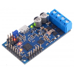
Sterownik silnika prądu stałego (DC) o napięciu pracy 4,5-28V i maksymalnym prądzie ciągłym 2,6A. Posiada możliwość łatwej realizacji pętli sprzężenia zwrotnego oraz liczne interfejsy sterujące. Pololu 3142
Brak towaru
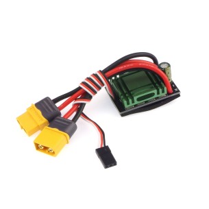
Dwukierunkowy kontroler prędkości ESC do silników szczotkowych. Może dostarczyć prąd o natężeniu 20 A i ma przewody zakończone złączem XT60. DFRobot DRI0047
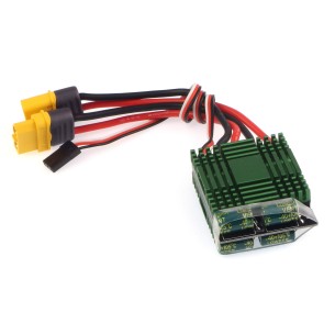
Dwukierunkowy kontroler prędkości (ESC) bez hamulca to zaawansowane urządzenie do sterowania silnikami szczotkowymi, oferujące prąd ciągły do 40 A i chwilowy do 340 A, co zapewnia stabilne działanie i dynamiczną reakcję na obciążenie. Sterowanie sygnałem PPM umożliwia precyzyjną kontrolę prędkości i kierunku obrotów silnika, a radiator i złącze XT60 gwarantują bezpieczne użytkowanie i skuteczne chłodzenie.
Brak towaru
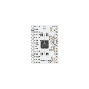
TMC5130A-BOB umożliwia wygodne testowanie i integrację sterowania silnikami krokowymi w aplikacjach wymagających precyzyjnego pozycjonowania i kontroli ruchu. Zintegrowane funkcje rampowania, interpolacji mikrokroków i enkodera czynią ją idealnym wyborem do zastosowań w automatyce, robotyce i systemach mechatronicznych.
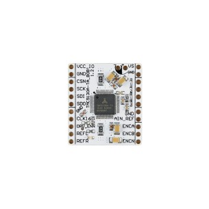
TMC5072-BOB to kompaktowa płytka wyprowadzeniowa z układem TMC5072, przeznaczona do szybkiego prototypowania rozwiązań z precyzyjnym sterowaniem ruchem. Wysoka rozdzielczość mikrokrokowa, wsparcie dla enkoderów oraz szeroki zakres napięcia zasilania czynią ją odpowiednim wyborem do projektów takich jak drukarki 3D, sterowniki osi CNC czy manipulatory robotyczne. TMC5072-BOB
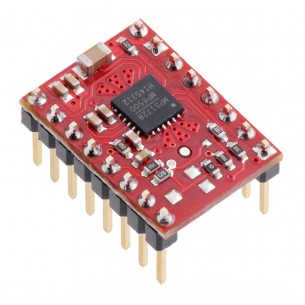
Sterownik silnika krokowego z układem MP6500 z potencjometrem do regulacji prądu. Pozwala na zasilanie silnika bipolarnego prądem do 1,5A na fazę bez użycia radiatora. Pololu 2967
Brak towaru
Sterownik silnika krokowego z układem MP6500, pozwala na zasilanie silnika bipolarnego prądem do 2A na fazę, bez użycia radiatora. Układ może być zasilany napięciem w zakresie 4,5...35V. Pololu 2969
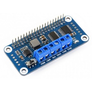
Nakładka ze sterownikiem silników TB6612FNG oraz sterownikiem PWM PCA9685 przeznaczona do minikomputerów Raspberry Pi. Płytka wyposażona została w złącze 40-pin charakterystyczne dla Raspberry Pi. Waveshare Motor Driver HAT
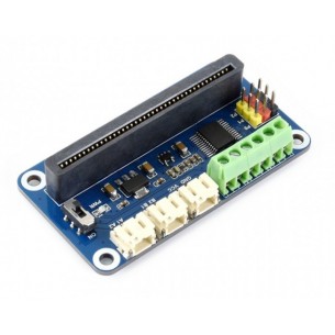
Moduł rozszerzeń przeznaczony do współpracy z płytką edukacyjną micro:bit. Może sterować 3 serwomechanizmami i 2 silnikami prądu stałego. Waveshare Motor Driver for micro:bit
Brak towaru
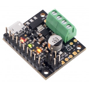
Pololu G2 18v15 High Power to miniaturowy sterownik silnika DC. Zasilanie sterownika: 6,5...30 V. Wydajność prądowa modułu: 15 A. Moduł posiada zabezpieczenie przed napięciem wstecznym i przepięciami. Pololu 1362
Brak towaru
Pololu G2 18v15 High Power to miniaturowy sterownik silnika DC. Zasilanie sterownika: 6,5...30 V. Wydajność prądowa modułu: 15 A. Moduł posiada zabezpieczenie przed napięciem wstecznym i przepięciami. Pololu 1363
Pololu G2 24v12 High Power to miniaturowy sterownik silnika DC. Zasilanie sterownika: 6,5...30V. Wydajność prądowa modułu: 12A. Moduł posiada zabezpieczenie przed napięciem wstecznym i przepięciami. Pololu 1364
A4988 Stepper Motor Driver Carrier with Voltage Regulators umożliwia precyzyjne sterowanie silnikami krokowymi z wykorzystaniem mikrokroku i regulacji prądu. Moduł sprawdza się w aplikacjach wymagających dokładnego pozycjonowania oraz prostej integracji z popularnymi mikrokontrolerami. Pololu 1183