


49,30 zł Netto
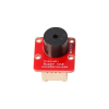
Wydajny, kompaktowy i prosty w użyciu sterownik silnika DC, idealny do projektów robotycznych, automatyki oraz prototypów edukacyjnych. Dzięki szerokiemu zakresowi napięć, niewielkiej liczbie wymaganych linii sterujących i wbudowanym zabezpieczeniom doskonale sprawdzi się zarówno u początkujących, jak i zaawansowanych konstruktorów szukających nowoczesnej alternatywy dla starszych mostków H. Pololu 2136
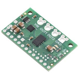
Kompaktowa płytka sterownika silnika DC oparta na układzie DRV8801 firmy Texas Instruments. Umożliwia dwukierunkowe sterowanie jednym szczotkowym silnikiem prądu stałego przy napięciu zasilania silnika od 8 do 36 V. Jest to nowoczesna i wydajna alternatywa dla klasycznych sterowników takich jak L293D czy L298N, oferująca wyższą sprawność, mniejsze straty mocy oraz wbudowane zabezpieczenia.
Sterowanie odbywa się za pomocą prostego interfejsu: jednego pinu do wyboru kierunku obrotów oraz jednego pinu PWM do regulacji prędkości.
Cechy
Producent BTC Korporacja sp. z o. o. Lwowska 5 05-120 Legionowo Polska sprzedaz@kamami.pl 22 767 36 20
Osoba odpowiedzialna BTC Korporacja sp. z o. o. Lwowska 5 05-120 Legionowo Polska sprzedaz@kamami.pl 22 767 36 20
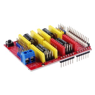
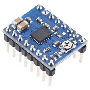
Sterownik A4988 to moduł do sterowania silnikami krokowymi bipolarnymi z mikrokrokowaniem do 1/16 kroku, obsługujący napięcie do 35 V i prąd do 2 A. Znajduje zastosowanie w drukarkach 3D, maszynach CNC i projektach wymagających precyzyjnego sterowania ruchem.
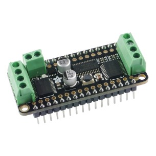
Płytka rozszerzeń FeatherWing do sterowania silnikami DC, krokowymi oraz serwomechanizmami, oparta na kontrolerze PWM PCA9685 i mostkach H TB6612FNG. Adafruit 3243
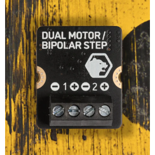
Kompaktowy sterownik silników przeznaczony do pracy z platformą Pimoroni Yukon, umożliwiający obsługę dwóch silników DC lub jednego bipolarnego silnika krokowego. Zastosowany układ DRV8424P zapewnia stabilne sterowanie przy napięciu zasilania od 5 do 17 V oraz prądzie do 1,6 A ciągłego na kanał. Moduł oferuje regulowane ograniczenie prądu, zabezpieczenia termiczne i detekcję błędów. Pimoroni PIM693
Brak towaru
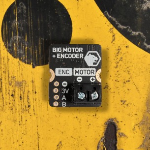
Wydajny sterownik przeznaczony do obsługi jednego silnika szczotkowego DC z enkoderem w systemie Pimoroni Yukon. Oferuje prąd ciągły do 8 A oraz szczytowy do 12 A przy napięciu zasilania od 5 do 17 V, co czyni go odpowiednim do wymagających projektów robotycznych. Moduł zapewnia precyzyjną kontrolę dzięki obsłudze enkodera oraz wbudowanym czujnikom prądu, temperatury i błędów. Pimoroni PIM691
Kompaktowy moduł do sterowania dwoma silnikami DC, 6,5–37 V, ciągły prąd 12 A na kanał, szczytowy 70 A, z zabezpieczeniami i wskaźnikiem stanu. DFRobot DFR0601
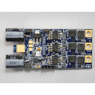
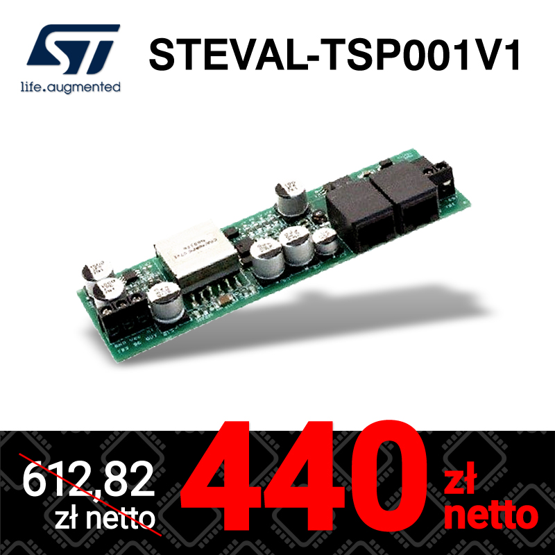
Kompaktowy i wydajny moduł regulatora ESC przeznaczony do silników BLDC i PMSM, idealny dla dronów wyścigowych i lekkich platform latających. Wyposażony w mikrokontroler STM32F303 z obsługą sensorless FOC oraz zaawansowany pomiar prądu 3-shunt, zapewnia płynną pracę i wysoką efektywność. Obsługuje zasilanie 3S–6S LiPo, prądy do 20 A RMS oraz komunikację przez PWM, UART, CAN i I²C, co ułatwia integrację z kontrolerami lotu. STMicroelectronics STEVAL-ESC001V1
Brak towaru
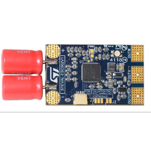
Kompaktowa moduł regulatora ESC przeznaczona do silników BLDC, idealna dla dronów i mobilnych konstrukcji. Wyposażona w układ STSPIN32F0A oraz tranzystory o bardzo niskiej rezystancji RDS(on), zapewnia wydajną pracę i prądy do 20 A. Obsługuje pakiety LiPo 2S–6S i oferuje precyzyjne sterowanie bezczujnikowe dzięki detekcji BEMF. STMicroelectronics STEVAL-ESC002V1
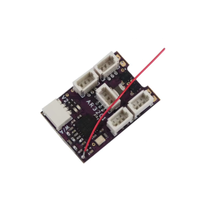
Sterownik silnika szczotkowego typu ESC z wbudowanym odbiornikiem FlySky, przeznaczony do zdalnego sterowania silnikami DC w modelach RC i projektach mobilnych, z obsługą sterowania kierunkiem i prędkością. modAR3201-F2
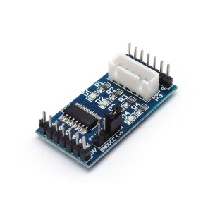
Moduł sterownika silnika krokowego z układem ULN2003 w obudowie SMD, zawierający 7 par tranzystorów Darlingtona ze wspólnym emiterem, przeznaczony do sterowania silnikami i przekaźnikami
Brak towaru
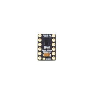
Moduł dwukanałowego sterownika silników umożliwiający sterowanie dwoma silnikami DC lub jednym bipolarnym silnikiem krokowym. Układ pracuje z napięciem silników do 11 V, obsługuje logikę 3,3 V i 5 V oraz zapewnia prąd wyjściowy do 1,2 A na kanał. Konstrukcja obejmuje dwa mostki H, obsługę PWM, tryby IN / IN i PHASE / ENABLE oraz zabezpieczenie nadprądowe i termiczne. Kamod Motor Driver DRV8835
Sterownik silników prądu stałego oparty na układzie Texas Instruments DRV8263H-Q1. Umożliwia sterowanie jednym silnikiem DC w dwóch kierunkach lub dwoma silnikami w jednym kierunku przy napięciu zasilania 4,5–65 V i ciągłym prądzie do 3,5 A (z możliwością limitu do 10 A). Moduł oferuje trzy tryby sterowania: Phase/Enable (PH/EN), PWM (IN/IN) oraz niezależne półmostki, a wbudowane czujniki prądu i funkcje ochronne chronią przed przeciążeniem, przegrzaniem i odwrotnym podłączeniem zasilania. Sterowanie logiką 3–5 V jest oddzielone od zasilania silnika, co zwiększa bezpieczeństwo i elastyczność integracji. Pololu 5238
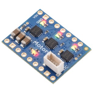
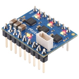
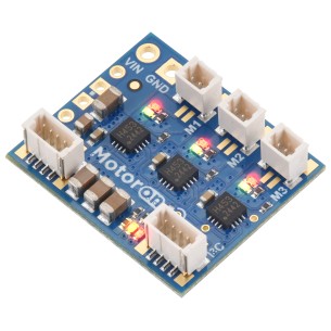
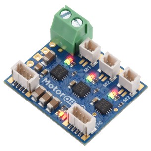
Sterownik umożliwiający niezależne sterowanie trzema silnikami prądu stałego za pomocą jednej magistrali I²C. Obsługuje napięcie zasilania silników w zakresie 4,5–44 V oraz prąd do 0,8 A ciągłego na kanał, co czyni go odpowiednim do wielu zastosowań robotycznych i mobilnych. Dzięki komunikacji I²C eliminuje konieczność generowania sygnałów PWM i znacząco oszczędza piny mikrokontrolera. Możliwość łączenia wielu sterowników na jednej magistrali pozwala łatwo skalować system do większej liczby silników. Pololu 5085
Sterownik umożliwiający niezależne sterowanie trzema silnikami prądu stałego za pomocą jednej magistrali I²C. Obsługuje napięcie zasilania silników w zakresie 4,5–44 V oraz prąd do 0,8 A ciągłego na kanał, co czyni go odpowiednim do wielu zastosowań robotycznych i mobilnych. Dzięki komunikacji I²C eliminuje konieczność generowania sygnałów PWM i znacząco oszczędza piny mikrokontrolera. Możliwość łączenia wielu sterowników na jednej magistrali pozwala łatwo skalować system do większej liczby silników. Pololu 5084
Sterownik umożliwiający niezależne sterowanie trzema silnikami prądu stałego za pomocą jednej magistrali I²C. Obsługuje napięcie zasilania silników w zakresie 4,5–44 V oraz prąd do 0,8 A ciągłego na kanał, co czyni go odpowiednim do wielu zastosowań robotycznych i mobilnych. Dzięki komunikacji I²C eliminuje konieczność generowania sygnałów PWM i znacząco oszczędza piny mikrokontrolera. Możliwość łączenia wielu sterowników na jednej magistrali pozwala łatwo skalować system do większej liczby silników. Pololu 5083
Sterownik umożliwiający niezależne sterowanie trzema silnikami prądu stałego za pomocą jednej magistrali I²C. Obsługuje napięcie zasilania silników w zakresie 4,5–44 V oraz prąd do 0,8 A ciągłego na kanał, co czyni go odpowiednim do wielu zastosowań robotycznych i mobilnych. Dzięki komunikacji I²C eliminuje konieczność generowania sygnałów PWM i znacząco oszczędza piny mikrokontrolera. Możliwość łączenia wielu sterowników na jednej magistrali pozwala łatwo skalować system do większej liczby silników. Pololu 5082
Jednokanałowy sterownik bipolarnego silnika krokowego oparty na układzie MP6603, obsługujący mikrokroki do 1/8 kroku i pracujący przy napięciu 8-55 V. Moduł umożliwia sterowanie prądem faz do około 2 A ciągłego bez dodatkowego chłodzenia i do 4 A szczytowo, posiada regulację limitu prądu potencjometrem oraz interfejs zgodny w wielu zastosowaniach z popularnymi nośnikami A4988. Wersja z fabrycznie wlutowanymi pinami, umożliwiająca bezpośrednie podłączenie do płytki stykowej lub gniazd zgodnych z A4988. Pololu 5691
Wydajny, kompaktowy i prosty w użyciu sterownik silnika DC, idealny do projektów robotycznych, automatyki oraz prototypów edukacyjnych. Dzięki szerokiemu zakresowi napięć, niewielkiej liczbie wymaganych linii sterujących i wbudowanym zabezpieczeniom doskonale sprawdzi się zarówno u początkujących, jak i zaawansowanych konstruktorów szukających nowoczesnej alternatywy dla starszych mostków H. Pololu 2136