


zł49.30 tax excl.
DRV8801 Single Brushed DC Motor Driver Carrier
DRV8801 Single Brushed DC Motor Driver Carrier
This tiny breakout board for TI’s DRV8801 provides a modern alternative to classic motor drivers such as the L293D, SN754410, and L298N. It can deliver a continuous 1 A (2.8 A peak) to a single motor and offers a wide operating voltage range of 8 to 36 V. The DRV8801 features a simple two-pin speed/direction interface, current-sense feedback, and built-in protection against under-voltage, over-current, and over-temperature.
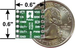 |
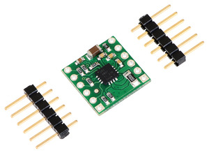
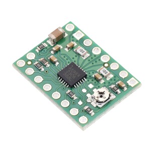
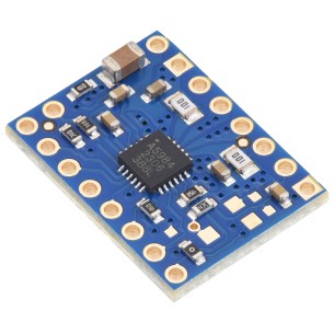
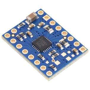
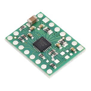
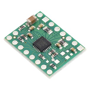
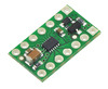
| DRV8801 single brushed DC motor driver carrier with dimensions. |
|---|
Texas Instruments’ DRV8801 is a tiny H-bridge motor driver IC that can be used for bidirectional control of a single brushed DC motor at 8 to 36 V. It can supply up to about 1 A continuously and can tolerate peak currents up to 2.8 A for a few seconds, making it a good choice for small motors that run on relatively high voltages. Since this board is a carrier for the DRV8801, we recommend careful reading of the DRV8801 datasheet (1MB pdf). The board ships populated with all of its SMD components, including the DRV8801.
For a dual-channel driver with a similar operating voltage range, please consider our A4990 carrier. For lower-voltage alternatives to the DRV8801, please consider our DRV8833 and DRV8835 dual motor driver carriers.
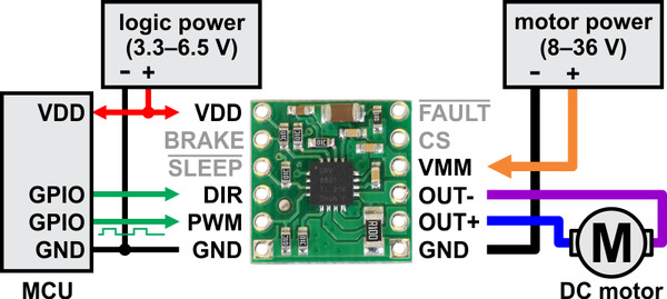 |
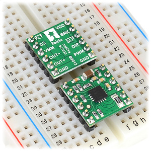
| Minimal wiring diagram for connecting a microcontroller to a DRV8801 single brushed DC motor driver carrier. |
|---|
In a typical application, power connections are made on one side of the board and control connections are made on the other. Aside from motor and power connections, the only required pins are DIR and PWM (called PHASE and ENABLE in the DRV8801 datasheet, respectively). A PWM signal can be applied to the PWM/ENABLE pin to achieve variable speed control in the direction determined by the state of the DIR/PHASE pin. The carrier board pulls PWM low by default, so the driver is only enabled when this pin is supplied with a high signal. The DIR pin does not have a defined default state, which means outputs could behave erratically if the DIR pin is left disconnected while the PWM pin is high.
The BRAKE pin determines whether the motor brakes or coasts when PWM pin is low (this pin is called MODE1 in the DRV8801 datasheet). The carrier board pulls it high, which corresponds to braking (both motor outputs are shorted together through ground). Setting the BRAKE pin low sets the outputs to coast whenever the PWM pin is low (both motor outputs are off). We generally recommend leaving this high while supplying a PWM signal to the PWM pin to get drive-brake (or “slow-decay”) operation, as this typically provides a more linear relationship between PWM duty cycle and motor speed than drive-coast (or “fast-decay”), and it can result in better performance at low duty cycles. The following truth table shows how the PWM, DIR, and BRAKE pins affect the driver outputs:
| DRV8801 Truth Table | |||||
|---|---|---|---|---|---|
| PWM/ENABLE | DIR/PHASE | BRAKE/MODE1 | OUT+ | OUT- | operating mode |
| PWM | 1 | 1 | PWM (H/L) | L | forward/brake at speed PWM % |
| PWM | 0 | 1 | L | PWM (H/L) | reverse/brake at speed PWM % |
| L | X | 1 | L | L | brake low (outputs shorted to ground) |
| PWM | 1 | 0 | PWM (H/OPEN) | PWM (L/OPEN) | forward/coast at speed PWM % |
| PWM | 0 | 0 | PWM (L/OPEN) | PWM (H/OPEN) | reverse/coast at speed PWM % |
| L | X | 0 | OPEN | OPEN | coast (outputs off) |
Note: When braking, the driver brakes low because the DRV8801’s MODE2 pin is pulled low on the carrier board. The MODE2 pin is not exposed to the user.
The SLEEP pin is pulled high on the board through a 10k resistor and can be left disconnected if you do not want to use the low-power sleep mode of the DRV8801.
The FAULT pin is an open-drain output that is driven low by the chip whenever an over-current, over-temperature, or under-voltage condition occurs. The carrier board includes a pull-up resistor on this pin, so no external pull-up is necessary. Note that the FAULT pin is a status-only signal that does not affect device functionality, so a low FAULT signal does not necessarily mean the driver outputs are disabled. For example, the driver will start operating normally once the motor supply voltage is above 8 V, but the FAULT output will be low until the motor supply voltage reaches approximately 12 V. Please see the datasheet for more information about how the DRV8801 responds to and reports faults.
The CS pin outputs an analog voltage proportional to the motor current (approximately 500 mV per A).
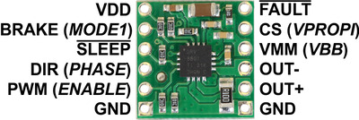 |
| PIN | Default State | Description |
|---|---|---|
| VMM/VBB | 8–36 V motor power supply connection. This pin called VBB in the DRV8801 datasheet. | |
| VDD | 3.3–6.5 V logic power supply connection. This pin is only used to power the FAULT, SLEEP, and BRAKE pull-up resistors on the carrier board. (The DRV8801 has its own internal logic voltage regulator.) | |
| GND | Ground connection points for the motor and logic power supplies. The control source and the motor driver must share a common ground. | |
| OUT+ | H-bridge output +. | |
| OUT- | H-bridge output -. | |
| DIR/PHASE | undefined | Logic input for controlling motor direction. |
| PWM/ENABLE | LOW | Logic input for enabling the driver outputs/controlling motor speed. A PWM signal can be applied to this pin. |
| BRAKE/MODE1 | HIGH | Logic input for controlling whether the driver brakes low or coasts when PWM pin is low. A logic high results in braking (slow-decay through ground). |
| SLEEP | HIGH | Logic input that puts the DRV8801 into a low-power sleep mode when low. |
| FAULT | Logic output that drives low when a fault occurs. The carrier board pulls this pin up to VDD. | |
| CS/VPROPI | Analog voltage output proportional to motor current (500 mV per A). |
The DRV8801 datasheet recommends a maximum continuous current of 2.8 A. However, the chip by itself will overheat at lower currents. For example, in our tests at room temperature with no forced air flow, the chip was able to deliver 2.8 A for a few seconds, 1.4 A for approximately 30 s, and 1.2 A for almost two minutes before the chip’s thermal protection kicked. A continuous current of 1 A per channel was sustainable for many minutes without triggering a thermal shutdown. The actual current you can deliver will depend on how well you can keep the motor driver cool. The carrier’s printed circuit board is designed to draw heat out of the motor driver chip, but performance can be improved by adding a heat sink. Our tests were conducted at 100% duty cycle; PWMing the motor will introduce additional heating proportional to the frequency.
This product can get hot enough to burn you long before the chip overheats. Take care when handling this product and other components connected to it.
|
|
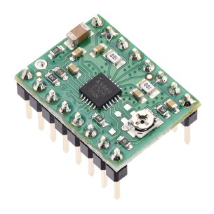
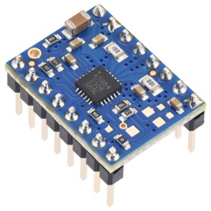
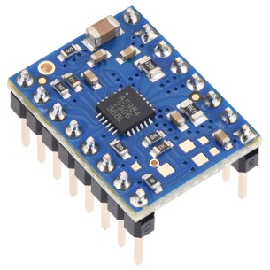
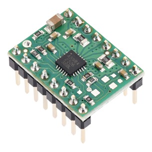
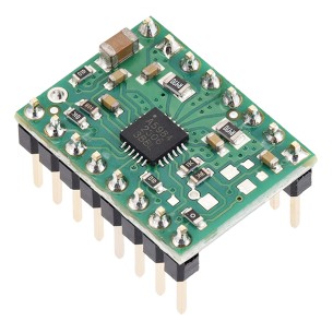
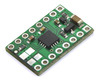
Two 1A—6-pin breakaway 0.1" male headers are included with the DRV8801 motor driver carrier, which can be soldered in to use the driver with perfboards, breadboards, or 0.1" female connectors. (The headers might ship as a single 1A—12 piece that can be broken in half.) The right picture above shows the two possible board orientations when used with these header pins (parts visible or silkscreen visible). You can also solder your motor leads and other connections directly to the board.
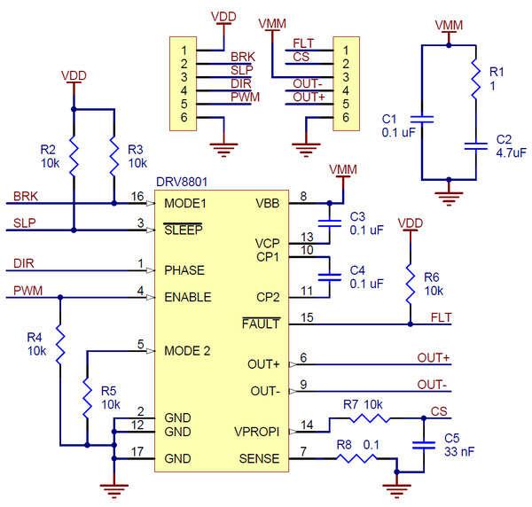 |
| Schematic diagram for the DRV8801 single brushed DC motor driver carrier. |
|---|
This schematic is also available as a downloadable pdf (157k pdf)
 |
DRV8835 Dual Motor Driver Carrier |
 |
DRV8833 Dual Motor Driver Carrier |
 |
TB6612FNG Dual Motor Driver Carrier |
Data sheet
Manufacturer BTC Korporacja sp. z o. o. Lwowska 5 05-120 Legionowo Poland sprzedaz@kamami.pl 22 767 36 20
Responsible person BTC Korporacja sp. z o. o. Lwowska 5 05-120 Legionowo Poland sprzedaz@kamami.pl 22 767 36 20
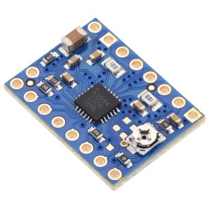
Module with a stepper motor driver based on the DRV8834 system. It allows you to power a bipolar motor with a current of up to 2 A per phase, without using a heat sink. The system can be powered with a voltage of up to 10.8 V. Pololu 2134
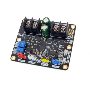
KAmod Motor Driver is an advanced DC motor controller powered by 6-30 V, enabling power regulation using the PWM method and control of the direction of rotation, compatible with analog and PWM signals from various sources, equipped with overload and thermal protections and soft start and stop functions
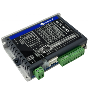
This advanced Nema 23 stepper motor controller from the CLRS series is designed for precision industrial applications with RS485 (Modbus RTU) network communication. It eliminates the risk of lost steps with closed-loop feedback and offers support for Profile Position, Velocity, Homing, and PR Mode with a 16-position point-to-point control table. The controller supports up to 31 axes on a single network, offers up to 7 A current, a 20 to 50 VDC supply voltage, and passive or active cooling, making it a reliable solution for robotics, automation, and CNC systems. CL2C-RS57
No product available!
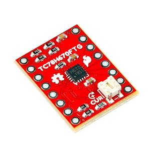
A compact controller that enables precise control of bipolar stepper motors. It offers high precision movement thanks to the ability to control a stepper motor with a resolution of up to 1/128 steps and two control interfaces - clock-in step control and serial commands. SparkFun ROB-25167
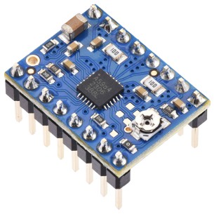
Compact and efficient module designed for precise control of bipolar stepper motors, offering microstepping down to 1/32 step and maximum current up to 2 A in peak mode. Thanks to advanced features such as QuietStep (APFD) algorithm, built-in protections and pin compatibility with A4988, it is perfect for hobby, educational and industrial projects. Blue Edition version with four-layer board and 2 oz copper provides better heat dissipation, increasing reliability of operation even at higher loads. Pololu 5340
Compact and efficient module designed for precise control of bipolar stepper motors, offering microstepping down to 1/32 step and maximum current up to 2 A in peak mode. Thanks to advanced features such as QuietStep (APFD) algorithm, built-in protections and pin compatibility with A4988, it is perfect for hobby, educational and industrial projects. Blue Edition version with four-layer board and 2 oz copper provides better heat dissipation, increasing reliability of operation even at higher loads. Pololu 5341
Driver for bipolar stepper motors with STEP/DIR interface, microstepping up to 1/16 and adjustable current via onboard potentiometer, compatible with 3.3 V and 5 V logic, version without soldered headers. Pololu 5342
Driver for bipolar stepper motors with STEP/DIR interface, microstepping up to 1/16 and adjustable current via onboard potentiometer, compatible with 3.3 V and 5 V logic, includes soldered header pins. Pololu 5343
Driver for bipolar stepper motors with STEP/DIR interface, microstepping up to 1/16 and maximum current up to 1.5 A at 5 V or 1 A at 3.3 V, version without soldered headers. Pololu 5344
Driver for bipolar stepper motors with STEP/DIR interface, microstepping up to 1/16, soldered header pins and maximum current up to 1.5 A at 5 V or 1 A at 3.3 V. Pololu 5345
Driver for bipolar stepper motors with STEP/DIR interface, microstepping up to 1/16 and maximum current up to 1 A at 5 V logic or 660 mA at 3.3 V logic. Pololu 5346
Stepper motor driver based on the A5984 IC, with soldered header pins, designed for controlling bipolar stepper motors in electronics and robotics projects. Pololu 5347
A5984 stepper motor driver for bipolar stepper motors, supply voltage 8–40 V, fixed current limit of 750 mA at 5 V or 500 mA at 3.3 V, microstepping up to 1/32, and STEP/DIR interface. Pololu 5348
A5984 stepper motor driver for bipolar stepper motors, supply voltage 8–40 V, fixed current limit of 750 mA at 5 V or 500 mA at 3.3 V, microstepping up to 1/32, and STEP/DIR interface. Version with soldered header pins. Pololu 5349
A5984 stepper motor driver for bipolar stepper motors, supply voltage 8-40 V, fixed current limit 500 mA at 5 V or 330 mA at 3.3 V, microstepping up to 1/32 and STEP/DIR interface. Pololu 5350
A5984 stepper motor driver for bipolar stepper motors, supply voltage 8-40 V, fixed current limit 500 mA at 5 V or 330 mA at 3.3 V, microstepping up to 1/32 and STEP/DIR interface. Version with soldered header pins. Pololu 5351
DRV8801 Single Brushed DC Motor Driver Carrier