


zł924.30 tax excl.
Dual VNH3SP30 Motor Driver Carrier MD03A
Dual VNH3SP30 Motor Driver Carrier MD03A
If you are looking to drive two high-power motors through one compact unit, these dual VNH3SP30 motor driver carriers are perfect for you. With these boards, it’s easy to get a medium-sized, differential drive robot running in no time. The VNH3 version is a lower-cost option than its VNH2 counterpart.
 |
The Pololu dual high-power motor drivers are compact carriers for the VNH3SP30 and VNH2SP30 motor driver integrated circuits from ST. The board incorporates most of the components of the typical application diagram on page 8 of the VNH2SP30 datasheet, including pull-up and current-limiting resistors and a FET for reverse battery protection. (The current sense circuit is populated on both versions of the board, but only the VNH2SP30 supports current sense.) To keep the number of I/O lines down, the two enable/diagnostic lines on each chip are tied together. All you need to add is a microcontroller or other control circuit to turn the H-Bridges on and off.
Please note that we offer several other products based on these same chips, including single carrier boards for controlling one motor, the qik 2s12v10 dual serial motor controller, the TReX motor controller, the jrk 12v12 USB motor controller with feedback, and the Orangutan X2 robot controller. We also have a family of higher-power motor drivers that can deliver more current over a wider operating voltage range.
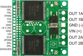 |
In a typical application, the power connections are made on one end of the board, and the control connections are made on the other end. +5 volts must be supplied to the board through the smaller 0.1"-spaced pins; the input voltage is available at those pins as well, but the connection is not intended for currents exceeding a few amps. The diagnostic pins can be left disconnected if you do not want to monitor the fault conditions of the motor drivers. INA and INB control the direction of each motor, and the PWM pins turns the motors on or off. For the VNH2SP30 version, the current sense (CS) pins will output approximately 0.13 volts per amp of output current. If you want to add current sensing to the VNH3SP30 version, or if you want higher-accuracy current sensing with the VNH2SP30 version, please consider our ±30A ACS714 current sensor carrier.
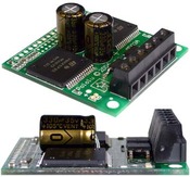 |
The dual motor driver PCB includes provisions for installing up to three large capacitors to limit disturbances on the main power line. Two 10mm radial capacitors may be mounted between the motor driver ICs, and an axial capacitor may be mounted between the ICs and power connections. It is generally not necessary to use all three capacitors; two radial capacitors are included with each unit. For applications that require a low profile, a single capacitor can be installed on its side as shown in the picture to the right.
Note: A 15-pin male header, three 2-pin terminal blocks, and two electrolytic capacitors are included but not soldered onto the boards. No printed documentation is shipped with these items; please see the VNH3SP30 and VNH2SP30 datasheets linked under the Resources tab.
| VNH3SP30 | VNH2SP30 | |
|---|---|---|
| Operating supply voltage (Vcc) | 5.5 – 36 V* | 5.5 – 16 V |
| Maximum current rating | 30 A | 30 A |
| MOSFET on-resistance (per leg) | 34 mΩ | 19 mΩ |
| Maximum PWM frequency | 10 kHz | 20 kHz |
| Current sense | none | approximately 0.13 V/A |
| Over-voltage shutoff | 36 V* | 16 V minimum (19 V typical) |
| Time to overheat at 20 A** | 8 seconds | 35 seconds |
| Time to overheat at 15 A** | 30 seconds | 150 seconds |
| Current for infinite run time** | 9 A | 14 A |
*Manufacturer specification. In our experience, shoot-through currents make PWM operation impractical above 16 V.
**Typical results using Pololu motor driver carrier with 100% duty cycle at room temperature.
The motor drivers have maximum current ratings of 30 A continuous. However, the chips by themselves will overheat at lower currents (see table above for typical values). The actual current you can deliver will depend on how well you can keep the motor drivers cool. The carrier printed circuit board is designed to draw heat out of the motor driver chips, but performance can be improved by adding a heat sink. In our tests, we were able to deliver short durations (on the order of milliseconds) of 30 A and several seconds of 20 A without overheating. At 6 A, the chip gets just barely noticeably warm to the touch. For high-current installations, the motor and power supply wires should also be soldered directly instead of going through the supplied terminal blocks, which are rated for up to 15 A.
This product can get hot enough to burn you long before the chip overheats. Take care when handling this product and other components connected to it.
Many motor controllers or speed controllers can have peak current ratings that are substantially higher than the continuous current rating; this is not the case with these motor drivers, which have a 30 A continuous rating and over-current protection that can kick in as low as 30 A (45 A typical). Therefore, the stall current of your motor should not be more than 30 A. (Even if you expect to run at a much lower average current, the motor can still draw high currents when it is starting or if you use low duty cycle PWM to keep the average current down.)
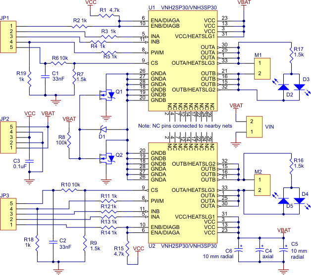 |
| Schematic of the Pololu Dual High Current Motor Driver Carrier |
|---|
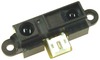 |
Sharp GP2Y0A21YK0F Analog Distance Sensor 10-80cm |
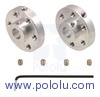 |
Pololu Universal Aluminum Mounting Hub for 6mm Shaft Pair, 4-40 Holes |
 |
Pololu 37D mm Metal Gearmotor Bracket Pair |
Data sheet
Manufacturer BTC Korporacja sp. z o. o. Lwowska 5 05-120 Legionowo Poland sprzedaz@kamami.pl 22 767 36 20
Responsible person BTC Korporacja sp. z o. o. Lwowska 5 05-120 Legionowo Poland sprzedaz@kamami.pl 22 767 36 20
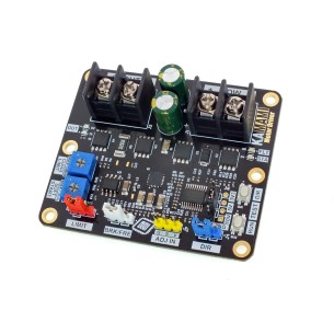
KAmod Motor Driver is an advanced DC motor controller powered by 6-30 V, enabling power regulation using the PWM method and control of the direction of rotation, compatible with analog and PWM signals from various sources, equipped with overload and thermal protections and soft start and stop functions
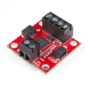
Module with 2-channel DC motor driver. It allows you to control the drive with a supply voltage from 3 to 11 V and a current of 1.2 A (1.5 A instantaneous). I2C communication. SparkFun ROB-15451
No product available!
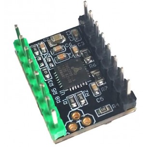
Module with bipolar stepper motor driver TC78H670FTG. It allows you to control the motor with an accuracy of 1/128 of a step with a voltage from 3.6 to 16 V and a current of up to 2 A. SparkFun ROB-16836
No product available!
Module with the TMC2209 bipolar stepper motor driver. It enables control with a supply voltage ranging from 4.75 to 29 V and a current of up to 2.8 A
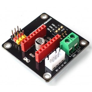
Compact expansion module compatible with DRV8825 and A4988 stepper motor drivers. It allows you to connect the module with the controller and convenient connection of other system components
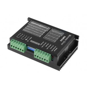
Stepper motor driver that can work with a voltage in the range from 20 to 50 V and a maximum current of 4.2 A. It allows you to configure the microstep in the range from 2 to 128. DM542
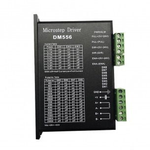
Stepper motor driver that can work with a voltage in the range from 20 to 50 V and a maximum current of 5.6 A. It allows you to configure the microstep in the range from 2 to 128. DM556
No product available!
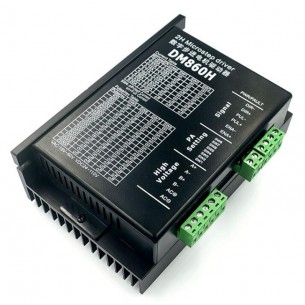
Stepper motor driver that can operate with a voltage in the range from 24 to 110 VDC or from 18 to 80 VAC and a maximum current of 7.2 A. It allows for microstep configuration in the range from 2 to 256. DM860H
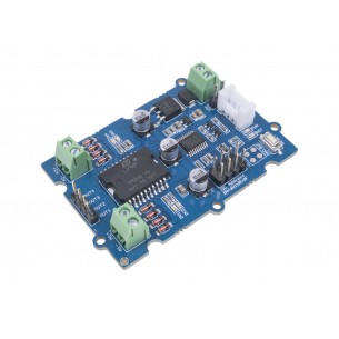
Module with 2-channel driver for DC motors L298P. The board is equipped with a Grove connector and communicates via the I2C interface. Seeed Studio 105020093
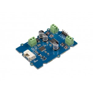
Module with TB6612FNG DC motors dual driver. The board is equipped with a Grove connector and communicates via the I2C interface. Seeed Studio 108020103
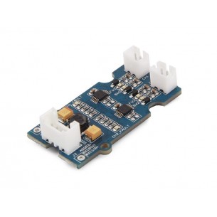
Module with two DRV8830 DC motor drivers. The board is equipped with a Grove connector and communicates via the I2C interface. Seeed Studio 105020010
No product available!
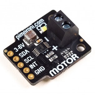
The module with the DRV8830 DC motor controller with a maximum current of 1 A. The board is equipped with a screw connector and communicates via the I2C interface. Pimoroni PIM479
Two-channel DC motor driver powered with the voltage from 2.5 to 12 V with a maximum continuous current of 0.8 A per channel. It can control a bipolar stepper motor
No product available!
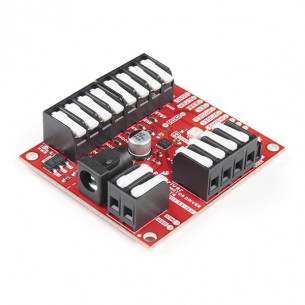
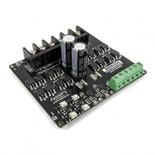
Two-channel driver of direct current (DC) motors with an operating voltage from 6 to 30 V and a maximum continuous current of 20 A. It can be controlled by a PWM signal or by means of built-in buttons. Cytron MDD20A
No product available!
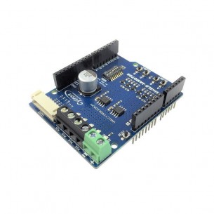
Shield with dual-channel DC motor driver for Arduino. It has an operating voltage from 7 to 30 V and a continuous current of up to 1.2 A. It can be controlled by a PWM signal or by means of built-in buttons. Cytron SHIELD-3AMOTOR
Single-channel DC motor driver with an operating voltage from 10 to 45 V and a continuous current up to 40 A. It can be controlled by an analog signal, PWM, UART, RC or by means of built-in buttons. Cytron MDS40B
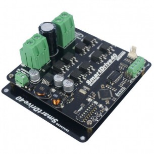
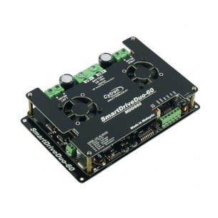
Two-channel driver for DC motors with an operating voltage from 7 to 45 V and a continuous current of up to 60 A. It can be controlled by an analog signal, PWM, UART, RC or by means of built-in buttons. Cytron MDDS60
No product available!
Dual VNH3SP30 Motor Driver Carrier MD03A