- Obecnie brak na stanie
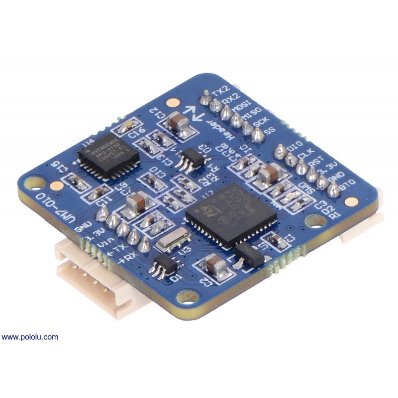


Overview
The UM7 orientation sensor is a third-generation Attitude and Heading Reference System (AHRS) from CH Robotics that produces attitude and heading estimates from triaxial accelerometer, rate gyro, and magnetometer data. Unlike a typical inertial measurement unit (IMU), which only provides raw sensor readings, the UM7 features an onboard microcontroller that combines sensor data using a sophisticated Extended Kalman Filter (EKF) to generate orientation estimates 500 times a second.
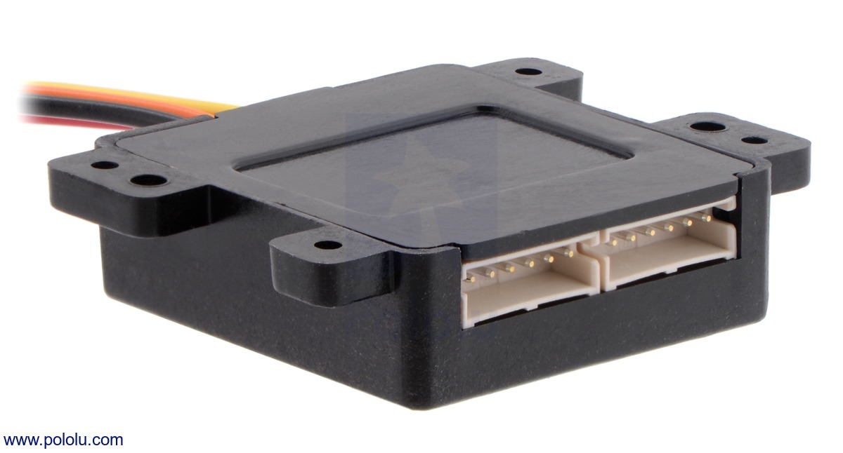
Two versions of the UM7 are available: the UM7 orientation sensor, which includes an enclosure, and the UM7-LT, which does not. The two versions are functionally equivalent, and both include a cable (even though it is only shown in one of the two pictures below).
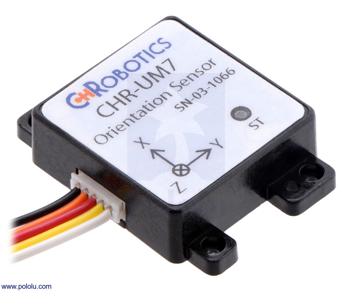
UM7 orientation sensor.
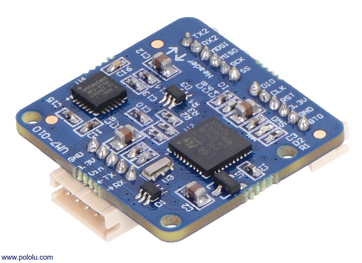
UM7-LT orientation sensor.
The UM7 features a number of improvements over its predecessor, the UM6, including higher gyro bias stability and lower noise, a new communication architecture for improved flexibility, optional NMEA packet transmission, UTC time-synchronization with external GPS, and support for third-order temperature compensation on all sensors. It takes advantage of newer MEMS (micro-electro-mechanical systems) technology that allows it to offer better performance at a lower price.
Connections for power and TTL serial communication can be made to the UM7 through a polarized five-pin male connector on one side, which mates with an included cable assembly. A pair of six-pin expansion headers on the other side of the board provide additional connectivity options, including an alternative SPI interface and a secondary serial interface that can be connected to an external GPS module (like our LS20031 GPS receiver). Additional cable assemblies for the expansion headers are not included.
Details for item #2741
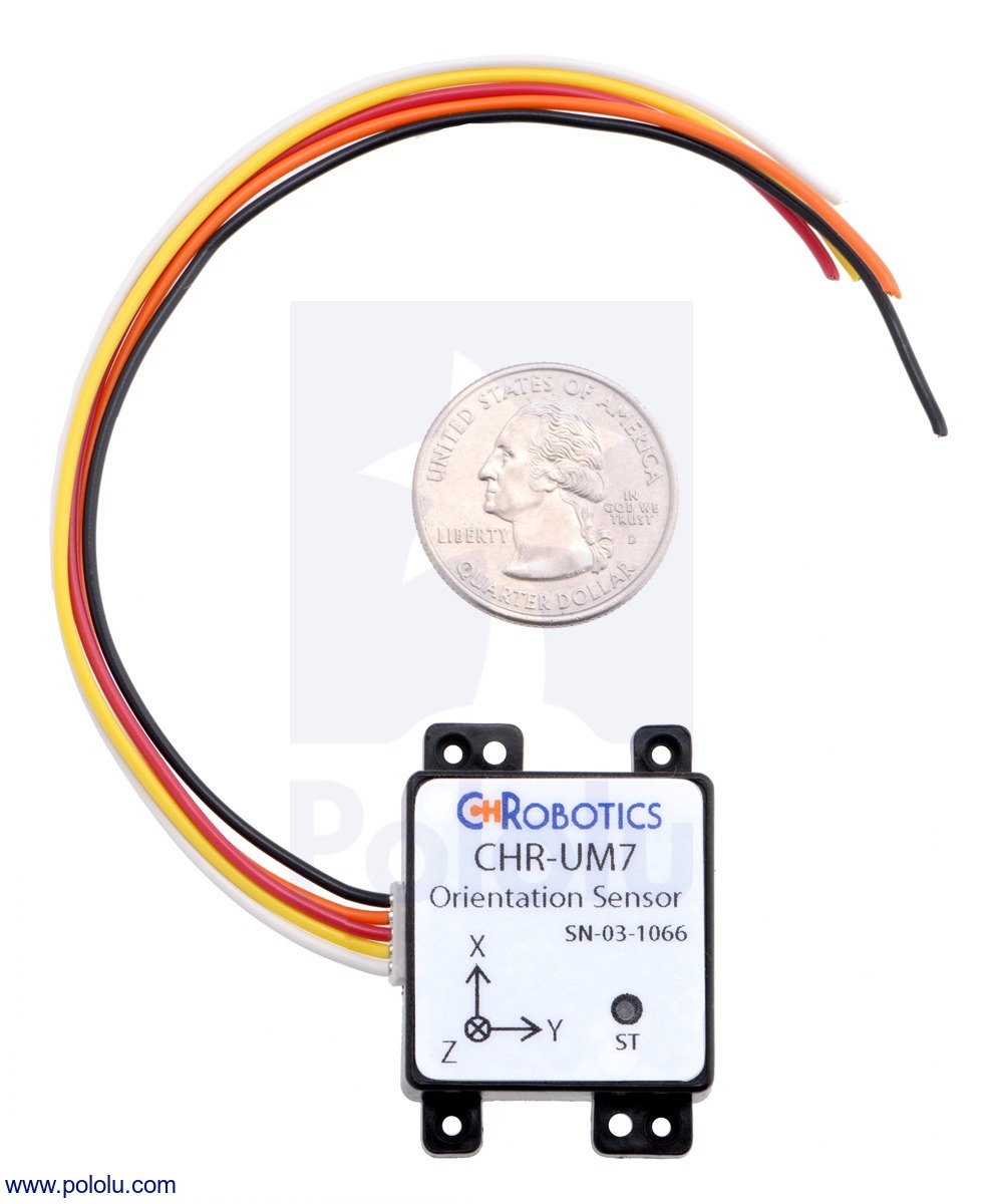
UM7 orientation sensor with included cable and U.S. quarter for size reference.
UM7 orientation sensor, bottom view showing optional expansion headers.
Product Comparison
We carry several inertial measurement and orientation sensors. The table below compares their capabilities:
| Product Name | Sensors | Estimation | Other | ||||||
|---|---|---|---|---|---|---|---|---|---|
| Gyros (3x) | Accels (3x) | Mag (3x) | Altitude | Roll | Pitch | Yaw | Quaternion | Enclosure | |
| Pololu MinIMU-9 v3 | YES | YES | YES | ||||||
| Pololu AltIMU-10 v4 | YES | YES | YES | YES | |||||
| CH Robotics UM7-LT Orientation Sensor | YES | YES | YES | YES | YES | YES | YES | ||
| CH Robotics UM7 Orientation Sensor | YES | YES | YES | YES | YES | YES | YES | YES | |
Features
Sensors and processing
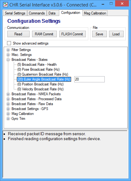
CHR Serial Interface.
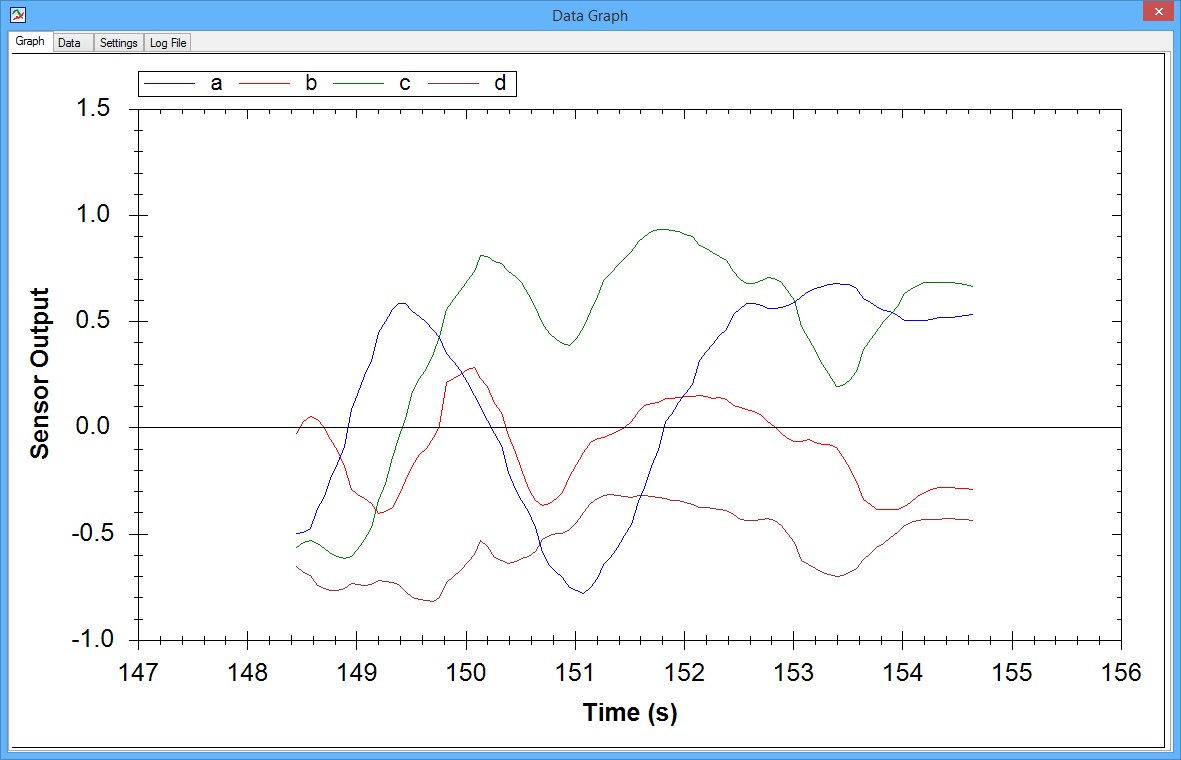
Graph of quaternions displayed by the CHR Serial Interface connected to a UM7/UM7-LT orientation sensor.
Communication
Specifications
Attitude and heading
Videos
In this video playlist, Caleb Chamberlain from CH Robotics shows how to get started with the UM7, configure its communication settings, and calibrate its magnetometer.
Specification
Dimensions
| Size: | 1.09″ × 1.12″ × 0.37″1 |
|---|---|
| Weight: | 7.5 g2 |
General specifications
| Interface: | TTL serial, SPI |
|---|---|
| Minimum operating voltage: | 4 V |
| Maximum operating voltage: | 5.5 V |
| Maximum logic voltage: | 3.3 V3 |
| Axes: | pitch (x), roll (y), and yaw (z) |
| Measurement range: | ±2000°/s (gyro) ±8 g (accelerometer) ±12 gauss (magnetometer) |
| Supply current: | 50 mA |
| Case/enclosure: | Y |
Notes:
Resources
File downloads

CHR Serial Interface.

Graph of quaternions displayed by the CHR Serial Interface connected to a UM7/UM7-LT orientation sensor.
(This software is open-source; CH Robotics will provide the source code upon request.)
Producent BTC Korporacja sp. z o. o. Lwowska 5 05-120 Legionowo Polska sprzedaz@kamami.pl 22 767 36 20
Osoba odpowiedzialna BTC Korporacja sp. z o. o. Lwowska 5 05-120 Legionowo Polska sprzedaz@kamami.pl 22 767 36 20
Uniwersalny programator ISP układów SPLD, CPLD i FPGA (Altera, Atmel, Lattice, Xilinx) i mikrokontrolerów AT89Sxxxx
Brak towaru
Uniwersalny programator ISP układów CPLD i FPGA (Altera, Xilinx) oraz mikrokontrolerów AVR i AT89Sxxxx
Brak towaru
Brak towaru
Brak towaru
Brak towaru
Brak towaru
Listwa stykowa prosta w kolorze czarnym, jednorzędowa, żeńska, 1x6, raster 2.54mm, THT, RoHS. PB16S
Brak towaru
ATmega8-16PU to mikrokontroler z rodziny AVR w obudowie DIP28W, wyposażony jest w pamięci: 8 kB Flash, 1 kB SRAM, 512 B EEPROM. Dodatkowe wyposażenie to: interfejs UART, interfejs SPI oraz TWI. Napięcie zasilania to 4,5..5,5 V, maksymalne taktowanie 16 MHz.
Brak towaru
ATmega16-16PU to mikrokontroler z rodziny AVR, w 40-nóżkowej obudowie DIP, wyposażony jest w pamięci: 16 kB Flash, 1 kB RAM, 512 B EEPROM. Zasilany jest napięciem 4,5..5,5 V, maksymalne taktowanie to 16 MHz. Na pokładzie są m.in.: 4 kanały PWM, interfejsy UART, SPI i TWI, 10-bitowy przetwornik A/C.
Brak towaru
ATmega32-16PU to mikrokontroler z rodziny AVR z pamięcami: 32 kB Flash, 2 kB RAM, 1 kB EEPROM. Obudowa to DIP40, zasilanie napięciami z zakresu 2,7..5,5 V, maksymalne taktowanie to 16 MHz.Wyposażony jest m.in. w: interfejsy SPI, UART i TWI, przetwornik A/C i 4 kanały PWM.
Brak towaru
Brak towaru
Brak towaru
Brak towaru
Brak towaru
Brak towaru
Brak towaru

Moduł orientacji UM7 jest systemem odniesienia położenia i kursu (AHRS), posiadającym akcelerometr, żyroskop i magnetometr; dane są łączone przy pomocy rozszerzonego filtru Kalmana, na wyjściu otrzymywane są estymaty polożenia i kursu. Pololu - 2741
