.png)



229,78 zł Netto
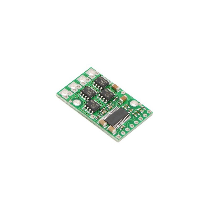
Pololu High-Power Motor Driver 18v15
Pololu High-Power Motor Driver 18v15
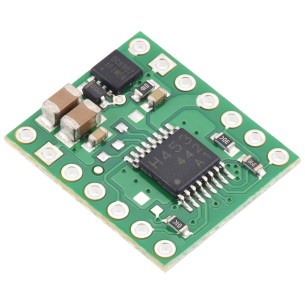
This discrete MOSFET H-bridge motor driver enables bidirectional control of one high-power DC brushed motor. The little 1.3×0.8-inch board supports a wide 5.5 to 30 V voltage range and is efficient enough to deliver a continuous 15 A without a heat sink.
 |
The Pololu high-power motor driver is a discrete MOSFET H-bridge designed to drive large DC brushed motors. The H-bridge is made up of one N-channel MOSFET per leg, and most of the board’s performance is determined by these MOSFETs (the rest of the board contains the circuitry to take user inputs and control the MOSFETs). The MOSFET datasheet is available under the “Resources” tab. The MOSFETs have an absolute maximum voltage rating of 30 V, and higher voltages can permanently destroy the motor driver. Under normal operating conditions, ripple voltage on the supply line can raise the maximum voltage to more than the average or intended voltage, so a safe maximum voltage is approximately 24 V.
Note: batteries that are nominally 24 V can be much higher than that when fully charged; this product is therefore not recommended for use with 24 V batteries unless appropriate measures are taken to limit the peak voltage.
The versatility of this driver makes it suitable for a large range of currents and voltages: it can deliver up to 15 A of continuous current with a board size of only 1.3" by 0.8" and no required heat sink. With the addition of a heat sink, it can drive a motor with up to about 21 A of continuous current. The module offers a simple interface that requires as little as two I/O lines while allowing for both sign-magnitude and locked-antiphase operation. Integrated detection of various short-circuit conditions protects against common causes of catastrophic failure; however, please note that the board does not include reverse power protection or any over-current or over-temperature protection.
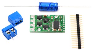
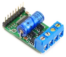
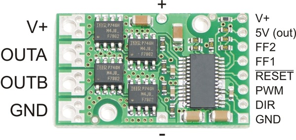
The motor and motor power connections are on one side of the board, and the control connections (5V logic) are on the other side. The motor supply should be capable of supplying high current, and a large capacitor should be installed close to the motor driver. The included axial capacitor can be installed directly on the board in the pins labeled '+' and '-' as shown below. Such installations are compact but might limit heat sinking options; also, depending on the power supply quality and motor characteristics, a larger capacitor might be required. There are two options for connecting to the high-power signals (V+, OUTA, OUTB, GND): large holes on 0.2" centers, which are compatible with the included terminal blocks, and pairs of 0.1"-spaced holes that can be used with perfboards, breadboards, and 0.1" connectors.
Warning: Take proper safety precautions when using high-power electronics. Make sure you know what you are doing when using high voltages or currents! During normal operation, this product can get hot enough to burn you. Take care when handling this product or other components connected to it.
The logic connections are designed to interface with 5V systems (5.5 V max); the minimum high input signal threshold is 3.5 V, so we do not recommend connecting this device directly to a 3.3 V controller. In a typical configuration, only PWM and DIR are required. The two fault flag pins (FF1 and FF2) can be monitored to detect problems (see the Fault Flag Table below for more details). The RESET pin, when held low, puts the driver into a low-power sleep mode and clears any latched fault flags. The V+ pin on the logic side of the board gives you access to monitor the motor’s power supply (it should not be used for high current). The board also provides a regulated 5 V pin which can provide a few milliamps (this is typically insufficient for a whole control circuit but can be useful as a reference or for very low-power microcontrollers).
 |
| PIN | Default State | Description |
|---|---|---|
| V+ | This is the main 5.5 – 30 V motor power supply connection, which should typically be made to the larger V+ pad. The smaller V+ pad along the long side of the board is intended for a power supply capacitor, and the smaller V+ pad on the logic side of the board gives you access to monitor the motor’s power supply (it should not be used for high current). | |
| 5V (out) | This regulated 5V output provides a few milliamps. This output should not be connected to other external power supply lines. Be careful not to accidentally short this pin to the neighboring V+ pin while power is being supplied as doing so will instantly destroy the board! | |
| GND | Ground connection for logic and motor power supplies. | |
| OUTA | A motor output pin. | |
| OUTB | B motor output pin. | |
| PWM | LOW | Pulse width modulation input: a PWM signal on this pin corresponds to a PWM output on the motor outputs. |
| DIR | FLOAT | Direction input: when DIR is high current will flow from OUTA to OUTB, when it is low current will flow from OUTB to OUTA. |
| RESET | HIGH | The reset pin, when pulled low, puts the board into a low-power sleep mode and clears any latched fault flags. |
| FF1 | LOW | Fault flag 1 indicator: FF1 goes high when certain faults have occurred. See table below for details. |
| FF2 | LOW | Fault flag 2 indicator: FF2 goes high when certain faults have occurred. See table below for details. |
A 16-pin straight breakaway male header, one 150 uF capacitor, and two 2-pin 5mm terminal blocks are included with each motor driver. (Note: The terminals blocks are only rated for 15 A; for higher power applications, use thick wires soldered directly to the board.) Connecting a large capacitor across the power supply is recommended; one way to do it is between the '+' and '-' holes, as shown below. The two mounting holes are intended to be used with #2 screws (not included).
|
|
With the PWM pin held low, both motor outputs will be held low (a brake operation). With PWM high, the motor outputs will be driven according to the DIR input. This allows two modes of operation: sign-magnitude, in which the PWM duty cycle controls the speed of the motor and DIR controls the direction, and locked-antiphase, in which a pulse-width-modulated signal is applied to the DIR pin with PWM held high.
In locked-antiphase operation, a low duty cycle drives the motor in one direction, and a high duty cycle drives the motor in the other direction; a 50% duty cycle turns the motor off. A successful locked-antiphase implementation depends on the motor inductance and switching frequency smoothing out the current (e.g. making the current zero in the 50% duty cycle case), so a high PWM frequency might be required.
| Motor Driver Truth Table | ||||
|---|---|---|---|---|
| PWM | DIR | OUTA | OUTB | Operation |
| H | L | L | H | Forward |
| H | H | H | L | Backward |
| L | X | L | L | Brake |
The motor driver supports PWM frequencies as high as 40 kHz, though higher frequencies result in higher switching losses in the motor driver. Also, the driver has a dead time (when the outputs are not driven) of approximately 3 us per cycle, so high duty cycles become unavailable at high frequencies. For example, at 40 kHz, the period is 25 us; if 3 us of that is taken up by the dead time, the maximum available duty cycle is 22/25, or 88%. (100% is always available, so gradually ramping the PWM input from 0 to 100% will result in the output ramping from 0 to 88%, staying at 88% for inputs of 88% through 99%, and then switching to 100%.)
The motor driver has a peak current rating of 170 A. The peak ratings are for quick transients (e.g. when a motor is first turned on), and the continuous rating of 15 A is dependent on various conditions, such as the ambient temperature. The actual current you can deliver will depend on how well you can keep the motor driver cool. The driver’s printed circuit board is designed to draw heat out of the MOSFETs, but performance can be improved by adding a heat sink. With a heat sink the motor driver can be run at up to 21 A of continuous current. For more information on power dissipation see the data sheet for the MOSFETs on the Resources tab.
Warning: This motor driver has no over-current or over-temperature shut-off. Either condition can cause permanent damage to the motor driver. You might consider using an external current sensor, such as our ACS714 ±30A bidirectional current sensor carrier to monitor your current draw.
The motor driver can detect three different fault states, which are reported on the FF1 and FF2 pins. The detectable faults are short circuits on the output, under-voltage, and over-temperature. A short-circuit fault is latched, meaning the outputs will stay off and the fault flag will stay high, until the board is reset (RESET brought low). The under-voltage fault disables outputs but is not latched. The over-temperature fault provides a weak indication of the board being too hot, but it does not directly indicate the temperature of the MOSFETs, which are usually the first components to overheat. The fault flag operation is summarized below.
| Flag State | Fault Description | Disable Outputs | Latched Until Reset | |
|---|---|---|---|---|
| FF1 | FF2 | |||
| L | L | No fault | No | No |
| L | H | Short Circuit | Yes | Yes |
| H | L | Over Temperature | No | No |
| H | H | Under Voltage | Yes | No |
There are currently nine versions of the high-power motor driver. The three CS versions have the same pinout, and the six non-CS versions have the same pinout. The following table provides a comparison of the high-power motor drivers:
| Pololu high-power motor drivers | ||
|---|---|---|
| Name | Max nominal battery voltage (V) | Max continuous current (A) w/o heat sink |
| High-power motor driver 18v25 CS | 18 | 25 |
| High-power motor driver 18v25 | 18 | 25 |
| High-power motor driver 18v15 | 18 | 15 |
| High-power motor driver 24v23 CS | 28 | 23 |
| High-power motor driver 24v20 | 28 | 20 |
| High-power motor driver 24v12 | 28 | 12 |
| High-power motor driver 36v20 CS | 36 | 20 |
| High-power motor driver 36v15 | 36 | 15 |
| High-power motor driver 36v9 | 36 | 9 |
Note: Please consider our Simple Motor Controllers as alternatives to these motor drivers. They have very similar power characteristics and offer high-level interfaces (e.g. USB, RC hobby servo pulses, analog voltages, and TTL serial commands) that make them much easier to use for many applications.
Cechy
Producent
Osoba odpowiedzialna
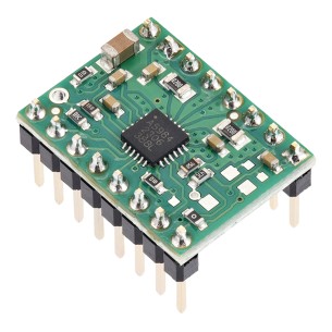
Sterownik silnika krokowego oparty na układzie A5984, z przylutowanymi złączami goldpin, przeznaczony do sterowania bipolarnymi silnikami krokowymi w projektach elektronicznych i robotycznych. Pololu 5347
Sterownik silnika krokowego A5984 do silników bipolarnych, zasilanie 8–40 V, stały limit prądu 750 mA przy 5 V lub 500 mA przy 3,3 V, mikrokrok do 1/32 oraz interfejs STEP/DIR. Pololu 5348
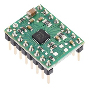
Sterownik silnika krokowego A5984 do silników bipolarnych, zasilanie 8–40 V, stały limit prądu 750 mA przy 5 V lub 500 mA przy 3,3 V, mikrokrok do 1/32 oraz interfejs STEP/DIR. Wersja z przylutowanymi złączami goldpin. Pololu 5349
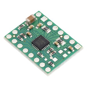
Sterownik silnika krokowego A5984 do silników bipolarnych, zasilanie 8-40 V, stały limit prądu 500 mA przy 5 V lub 330 mA przy 3,3 V, mikrokrok do 1/32 oraz interfejs STEP/DIR. Pololu 5350
Sterownik silnika krokowego A5984 do silników bipolarnych, zasilanie 8-40 V, stały limit prądu 500 mA przy 5 V lub 330 mA przy 3,3 V, mikrokrok do 1/32 oraz interfejs STEP/DIR. Wersja z przylutowanymi złączami goldpin. Pololu 5351
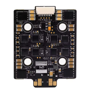
Kompaktowy i wydajny regulator prędkości ESC przeznaczony do modeli RC i wyścigów FPV, obsługujący akumulatory LiPo 4S–8S oraz stały prąd 60 A (chwilowy do 70 A). Dzięki standardowi montażowemu 20x20 mm, zapewnia trwałość, niezawodność i łatwą integrację nawet w ograniczonej przestrzeni. Zastosowanie oprogramowania AM32 i zmiennej częstotliwości PWM gwarantuje wysoką precyzję oraz płynną pracę silników w każdych warunkach. F60A mini
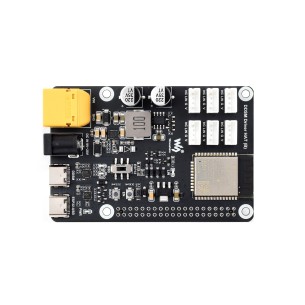
Waveshare DDSM Driver HAT (B) to zaawansowany sterownik silników piastowych DDSM400, oparty na ESP32, z obsługą komunikacji przewodowej (USB, UART) i bezprzewodowej (WiFi, ESP-NOW). Umożliwia sterowanie do 6 silników z wykorzystaniem poleceń JSON i integrację z Raspberry Pi, co czyni go odpowiednim rozwiązaniem dla robotyki mobilnej i projektów systemów wielosilnikowych.
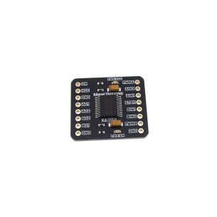
Dwukanałowy sterownik KAmod Motor Driver TB6612FNG z mostkami H MOSFET umożliwia precyzyjne sterowanie silnikami DC i krokowymi z częstotliwością PWM do 100 kHz. Kompaktowa konstrukcja, szeroki zakres napięcia i zabezpieczenia czynią moduł odpowiednim do projektów mobilnych, robotyki i automatyki.
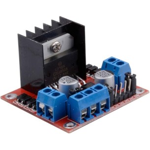
Moduł z układem L298N umożliwiający niezależne sterowanie dwoma silnikami DC lub jednym silnikiem krokowym, idealny do robotyki i projektów DIY. Obsługuje zasilanie od 7 V do 35 V i posiada wbudowany stabilizator 5 V, który może zasilać dodatkowe układy. Sterowanie odbywa się za pomocą pinów ENA, ENB oraz IN1–IN4, co pozwala regulować kierunek obrotów i prędkość. Moduł wyposażono w diody zabezpieczające i kondensatory filtrujące, co zapewnia stabilną i niezawodną pracę.
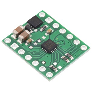
Mostek H umożliwiający sterowanie jednym silnikiem DC w obu kierunkach lub dwoma jednokierunkowymi przy napięciu od 4,5 do 44 V i prądzie ciągłym do 1,1 A. Moduł oferuje trzy tryby pracy (PH/EN, IN/IN, półmostki), wbudowane ograniczenie i pomiar prądu oraz zabezpieczenia przed przegrzaniem, przeciążeniem, zbyt niskim napięciem i odwrotną polaryzacją. Dzięki kompaktowej budowie, elastycznemu zasilaniu logiki (1,8–5,5 V) i prostemu sterowaniu świetnie sprawdza się w robotyce, automatyce i projektach hobbystycznych. Pololu 4972
Mostek H umożliwiający sterowanie jednym silnikiem DC w obu kierunkach lub dwoma jednokierunkowymi przy napięciu od 4,5 do 44 V i prądzie ciągłym do 1,3 A. Moduł oferuje trzy tryby pracy (PH/EN, IN/IN, półmostki), wbudowane ograniczenie i pomiar prądu oraz zabezpieczenia przed przegrzaniem, przeciążeniem, zbyt niskim napięciem i odwrotną polaryzacją. Dzięki kompaktowej budowie, elastycznemu zasilaniu logiki (1,8–5,5 V) i prostemu sterowaniu świetnie sprawdza się w robotyce, automatyce i projektach hobbystycznych. Pololu 4971
Brak towaru
Sterownik bipolarnego silnika krokowego pracujący przy napięciu od 8 do 50 V i prądzie do 8 A/fazę (11 A z chłodzeniem). Sterownik z układem DRV8711 i interfejsem SPI oferuje 9 trybów krokowych (do 1/256), konfigurację prądu, stall detection i zabezpieczenia przed zwarciem, przeciążeniem oraz odwrotną polaryzacją. Kompatybilny z logiką 1,8–5 V, świetnie sprawdza się w maszynach CNC, drukarkach 3D i robotyce. Pololu 3731
Płytka sterująca przeznaczona do silników serwo z serii DDSM, wyposażona w mikrokontroler ESP32, komunikację WiFi 2,4 GHz, interfejsy RS485 i UART oraz zintegrowany przetwornik 5 V do zasilania Raspberry Pi. Obsługuje do czterech silników DDSM115 lub DDSM315 albo czterech silników DDSM210, oferując sterowanie przewodowe i bezprzewodowe oraz obsługę poleceń JSON. DDSM Driver HAT (A)
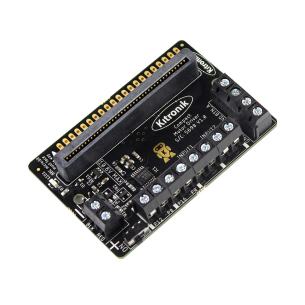
Płytka umożliwiająca jednoczesne sterowanie dwoma silnikami z pełną kontrolą kierunku i zatrzymania, idealna do robotycznych buggy i pojazdów edukacyjnych. Ma wbudowane zabezpieczenia przed zwarciem, przeciążeniem i przegrzaniem, a także stabilizowane wyjście 3 V zasilające micro:bit. Dzięki złączu Edge Connector i dodatkowym wyprowadzeniom można łatwo podłączać czujniki, przełączniki i akcesoria, rozszerzając funkcjonalność projektu. Programowanie wspierane jest przez dedykowane bloki MakeCode oraz obsługę w Pythonie Kitronik 5698
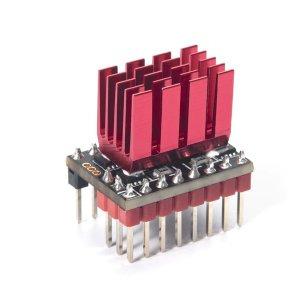
Kompaktowy sterownik silnika krokowego oparty na układzie TMC5160-TA firmy Trinamic, przeznaczony do precyzyjnego i cichego sterowania silnikami krokowymi w drukarkach 3D, ploterach CNC oraz innych systemach automatyki. Moduł pracuje z napięciem zasilania od 8 V do 35 V, oferując wysoką wydajność oraz stabilną pracę dzięki zaawansowanym algorytmom sterowania. Komunikacja odbywa się przez interfejs SPI, co umożliwia dokładną konfigurację parametrów pracy. Sterownik obsługuje mikrokroki do 1/256, zapewniając bardzo wysoką precyzję ruchu oraz płynność pracy silnika. BIGTREETECH TMC5160T V1.0
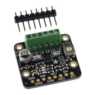
Sterownik silników krokowych, oferujący mikroki aż do 1/256 kroku, co zapewnia wyjątkową precyzję i płynność ruchu. Dzięki prostej obsłudze – wymagającej jedynie dwóch pinów z mikrokontrolera – oraz niskim napięciu pracy (1,8 do 10 V), doskonale nadaje się do energooszczędnych aplikacji mobilnych, robotycznych i DIY. Zintegrowane złącza, diody LED i potencjometr do regulacji prądu ułatwiają prototypowanie i bezpieczną integrację z popularnymi platformami takimi jak Arduino czy ESP32. Adafruit 6353
Pololu High-Power Motor Driver 18v15