


548,01 zł Netto
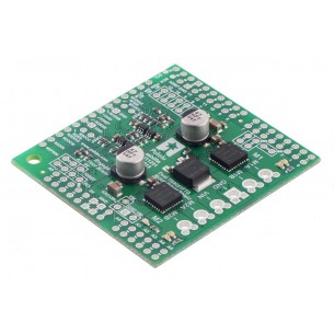
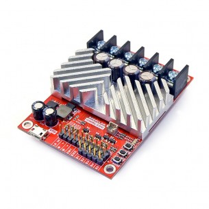
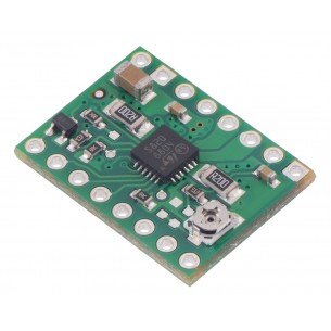
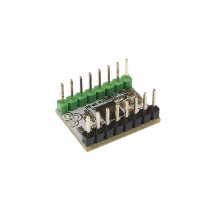
Pololu High-Power Motor Driver 24v23 CS

darmowa wysyłka na terenie Polski dla wszystkich zamówień powyżej 500 PLN

Jeśli Twoja wpłata zostanie zaksięgowana na naszym koncie do godz. 11:00

Każdy konsument może zwrócić zakupiony towar w ciągu 14 dni bez zbędnych pytań
Pololu High-Power Motor Driver 24v23 CS
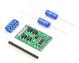
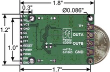
This discrete MOSFET H-bridge motor driver enables bidirectional control of one high-power DC brushed motor. The compact 1.8×1.2-inch board supports a wide 5.5 to 40 V voltage range and is efficient enough to deliver a continuous 23 A without a heat sink. This version outputs an analog voltage proportional to the motor current, and an extra control input allows for coasting in addition to the driving and braking offered by the other Pololu high-power motor drivers.
 |
The Pololu high-power motor driver is a discrete MOSFET H-bridge designed to drive large DC brushed motors. The H-bridge is made up of one N-channel MOSFET per leg, and most of the board’s performance is determined by these MOSFETs (the rest of the board contains the circuitry to take user inputs and control the MOSFETs). The MOSFET datasheet is available under the “Resources” tab. The MOSFETs have an absolute maximum voltage rating of 40 V; higher voltages can permanently destroy the motor driver. Under normal operating conditions, ripple voltage on the supply line can raise the maximum voltage to more than the average or intended voltage, so a safe maximum voltage is approximately 34 V.
Note: Charged battery voltages can be much higher than nominal voltages, so the maximum nominal battery voltage we recommend is 28 V unless appropriate measures are taken to limit the peak voltage.
The versatility of this driver makes it suitable for a large range of currents and voltages: it can deliver up to 23 A of continuous current with a board size of only 1.8" by 1.2" and no required heat sink. With the addition of a heat sink, it can drive a motor with up to about 37 A of continuous current. The module offers a simple interface that requires as few as two I/O lines while allowing for both sign-magnitude and locked-antiphase operation, and an optional third control input unique to this board allows for coasting. This board also features a current-sensing circuit that measures bidirectional motor current with a magnitude up to 30 A and outputs an analog voltage.
Integrated detection of various short-circuit conditions protects against common causes of catastrophic failure; however, please note that the board does not include reverse power protection or any over-current or over-temperature protection. We recommend you use the integrated current sensor to keep the driver from delivering more current than it can safely handle.
The motor and motor power connections are on one side of the board, and the control connections (5V logic) are on the other side. The motor supply should be capable of delivering the high current the motor will require, and a large capacitor should be installed between V+ and ground close to the motor driver to decrease electrical noise. Two axial capacitors are included and one or both can be installed by soldering them into the V+ and GND pins (labeled '+' and '-' on the bottom silkscreen) along the long edges of the board. Such installations are compact but might limit heat sinking options; also, depending on the power supply quality and motor characteristics, a larger capacitor might be required. There are two options for connecting to the high-power signals (V+, OUTA, OUTB, GND): large holes on 0.2" centers, which are compatible with the included terminal blocks, and pairs of 0.1"-spaced holes that can be used with perfboards, breadboards, and 0.1" connectors.
Warning: Take proper safety precautions when using high-power electronics. Make sure you know what you are doing when using high voltages or currents! During normal operation, this product can get hot enough to burn you. Take care when handling this product or other components connected to it.
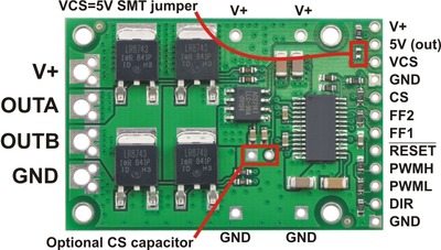
The logic connections are designed to interface with 5V systems (5.5 V max); the minimum high input signal threshold is 3.5 V, so we do not recommend connecting this device directly to a 3.3 V controller. In a typical configuration, only PWMH and DIR are required, but PWML can be used to enable coasting if both PWML and PWMH are driven low. PWML is pulled high and PWMH is pulled low internally. The two fault flag pins (FF1 and FF2) can be monitored to detect problems (see the Fault Flag Table below for more details). The RESET pin, when held low, puts the driver into a low-power sleep mode and clears any latched fault flags. The V+ pin on the logic side of the board gives you access to monitor the motor’s power supply or pass it on to low-current devices (it should not be used for high current). The board also provides a regulated 5V pin which can provide a few milliamps (this is typically insufficient for a whole control circuit but can be useful as a reference or for very low-power microcontrollers). This pin can be shorted to VCS to power the current sensor, or VCS can be supplied with 5 V externally. If the 5V output pin is used to power VCS, it should not be used for any other purpose as the current sensor will draw close to the limit of the current the 5V pin can supply. When the current sensor is powered by applying 5 V to VCS, the CS pin outputs 66 mV/A for currents between -30 and 30 A centered at 2.5 V (typical error is less than 1.5%).
 |
| PIN | Default State | Description |
|---|---|---|
| V+ | This is the main 5.5 – 30 V motor power supply connection, which should typically be made to the larger V+ pad. The smaller V+ pads along the long side of the board are intended for power supply capacitors, and the smaller V+ pad on the logic side of the board gives you access to monitor the motor’s power supply (it should not be used for high current). | |
| 5V (out) | This regulated 5V output provides a few milliamps. It can be shorted to VCS to power the current sensor. This output should not be connected to other external power supply lines. Be careful not to accidentally short this pin to the neighboring V+ pin while power is being supplied as doing so will instantly destroy the board! | |
| VCS | Connect 5 V to this pin to power the current sensor. | |
| GND | Ground connection for logic and motor power supplies. | |
| CS | ACS714 current sensor output (66 mV/A centered at 2.5 V). | |
| OUTA | A motor output pin. | |
| OUTB | B motor output pin. | |
| PWMH | LOW | Pulse width modulation input: a PWM signal on this pin corresponds to a PWM output on the motor outputs. |
| PWML | HIGH | Control input that enables coasting when both PWML and PWMH are low. See the “motor control options” section below for more information. |
| DIR | LOW | Direction input: when DIR is high current will flow from OUTA to OUTB, when it is low current will flow from OUTB to OUTA. |
| RESET | HIGH | The reset pin, when pulled low, puts the board into a low-power sleep mode and clears any latched fault flags. |
| FF1 | LOW | Fault flag 1 indicator: FF1 goes high when certain faults have occurred. See table below for details. |
| FF2 | LOW | Fault flag 2 indicator: FF2 goes high when certain faults have occurred. See table below for details. |
A 20-pin straight breakaway male header, two 100 uF capacitors, and two 2-pin 5mm terminal blocks are included with each motor driver. (Note: The terminals blocks are only rated for 15 A; for higher power applications, use thick wires soldered directly to the board.) Connecting large capacitors across the power supply is recommended; one way to do it is between the '+' and '-' holes, as shown below. The four mounting holes are intended to be used with #2 screws (not included).
|
|
The motor driver can be used in several different modes:
| Motor Driver Truth Table | |||||
|---|---|---|---|---|---|
| PWMH | PWML | DIR | OUTA | OUTB | Operation |
| H | H | L | GND | V+ | Forward |
| H | H | H | V+ | GND | Backward |
| L | H | X | GND | GND | Brake Low |
| H | L | X | V+ | V+ | Brake High |
| L | L | X | Z | Z | Coast |
X = don’t care (same for input H or L); Z = high impedance (outputs disconnected)
The motor driver supports PWM frequencies as high as 40 kHz, though higher frequencies result in higher switching losses in the motor driver. Also, the driver has a dead time (when the outputs are not driven) of approximately 3 us per cycle, so high duty cycles become unavailable at high frequencies. For example, at 40 kHz, the period is 25 us; if 3 us of that is taken up by the dead time, the maximum available duty cycle is 22/25, or 88%. (100% is always available, so gradually ramping the PWM input from 0 to 100% will result in the output ramping from 0 to 88%, staying at 88% for inputs of 88% through 99%, and then switching to 100%.)
The motor driver can tolerate peak currents in excess of 200 A. The peak current ratings are for quick transients (e.g. when a motor is first turned on), and the continuous rating of 23 A is dependent on various conditions, such as the ambient temperature. The main limitation comes from heating and power dissipation; therefore, at high currents, the motor driver will be extremely hot, and performance can be improved by adding heat sinks or otherwise cooling the board. The driver’s printed circuit board is designed to draw heat out of the MOSFETs, but performance can be improved by adding a heat sink. The MOSFETs have a theoretical maximum continuous current of 90A at 25°C, but dissipating enough heat to keep the MOSFET at this temperature is impractical for most applications; close to 40 A of continuous current should be achievable without too extravagant of a heat sink. For more information on power dissipation see the data sheet for the MOSFETs on the Resources tab.
Because there is no internal temperature limiting on the motor driver, the entire system should be designed to keep the load current below the 23 A limit. An easy way to achieve this is to select a motor with a stall current below that limit. However, because a good motor can have stall currents dozens of times higher than the typical operating current, motors with stall currents that are hundreds of amps can be used with this driver as long as the running current is kept low. For example, a motor with a 100 A stall current might run well at 10 A, leaving a safe margin for the current to double for several minutes at a time or to triple for several seconds. If the motor does stall completely for a prolonged period, however, the motor or driver are likely to burn out.
Warning: This motor driver has no over-current or over-temperature shut-off. Either condition can cause permanent damage to the motor driver. We recommend you use the current-sense output CS to monitor your current draw if your application will put the driver close to its limits of operation.
The motor driver can detect three different fault states, which are reported on the FF1 and FF2 pins. The detectable faults are short circuits on the output, under-voltage, and over-temperature. A short-circuit fault is latched, meaning the outputs will stay off and the fault flag will stay high, until the board is reset (RESET brought low). The under-voltage fault disables outputs but is not latched. The over-temperature fault provides a weak indication of the board being too hot, but it does not directly indicate the temperature of the MOSFETs, which are usually the first components to overheat. The fault flag operation is summarized below.
| Flag State | Fault Description | Disable Outputs | Latched Until Reset | |
|---|---|---|---|---|
| FF1 | FF2 | |||
| L | L | No fault | No | No |
| L | H | Short Circuit | Yes | Yes |
| H | L | Over Temperature | No | No |
| H | H | Under Voltage | Yes | No |
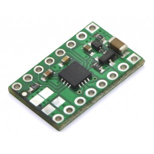
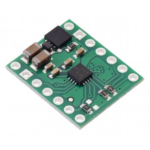
There are currently nine versions of the high-power motor driver. The three CS versions have the same pinout, and the six non-CS versions have the same pinout. The following table provides a comparison of the high-power motor drivers:
| Pololu high-power motor drivers | ||
|---|---|---|
| Name | Max nominal battery voltage (V) | Max continuous current (A) w/o heat sink |
| High-power motor driver 18v25 CS | 18 | 25 |
| High-power motor driver 18v25 | 18 | 25 |
| High-power motor driver 18v15 | 18 | 15 |
| High-power motor driver 24v23 CS | 28 | 23 |
| High-power motor driver 24v20 | 28 | 20 |
| High-power motor driver 24v12 | 28 | 12 |
| High-power motor driver 36v20 CS | 36 | 20 |
| High-power motor driver 36v15 | 36 | 15 |
| High-power motor driver 36v9 | 36 | 9 |
Note: Please consider our Simple Motor Controllers as alternatives to these motor drivers. They have very similar power characteristics and offer high-level interfaces (e.g. USB, RC hobby servo pulses, analog voltages, and TTL serial commands) that make them much easier to use for many applications.
Cechy
Osoba odpowiedzialna BTC Korporacja sp. z o. o. Lwowska 5 05-120 Legionowo Polska sprzedaz@kamami.pl 22 767 36 20
Sterownik silników DC, który pozwala na kontrolowanie ruchu dwóch napędów za pomocą interfejsu I2C. Płytka bez złączy . Pololu 5041
Brak towaru
Dwukanałowy sterownik silników DC zasilany napięciem od 2,5 do 12 V o maksymalnym prądzie ciągłym 0,8 A na kanał. Może sterować bipolarnym silnikiem krokowym
Podwójny sterownik silników DC przeznaczony dla Arduino, który umożliwia zasilanie silnika napięciem w zakresie 4,5-28V i poborze prądu przy pracy ciągłej 2,6A (5A w szczycie) dwóch silników DC. Pololu 2520
Podwójny sterownik silników pozwalający na sterowanie dwóch silników DC napięciem 2,7-10,8V i prądem ciągłym 1,2A na kanał. Pololu 2130
Brak towaru
Moduł ze sterownikiem silnika DC DRV8876. Może współpracować z silnikami zasilanymi napięciem od 4,5 do 37 V i poborze prądu do 1,1 A. Pololu 4037
Moduł sterownika silnika krokowego DRV8825 dla Arduino. Pozwala na sterowanie dwoma napędami, wyposażony w złącze XBee. DFRobot DRI0023
Brak towaru
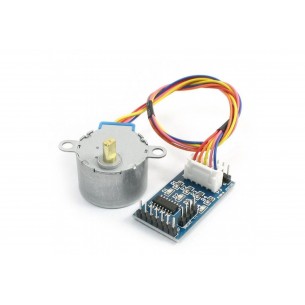
Zestaw składający się z modułu sterownika silnika krokowego opartego na układzie ULN2003 oraz silnika krokowego zasilanego napięciem 5V.
Brak towaru
Sterownik silnika prądu stałego (DC) o napięciu pracy 6,5-40V i maksymalnym prądzie ciągłym 21A. Posiada możliwość łatwej realizacji pętli sprzężenia zwrotnego oraz liczne interfejsy sterujące. Pololu 3149
RoboClaw 2x15A Motor Controller (V5D) to dwukanałowy sterownik silników prądu stałego (DC), napięcie pracy: 6-34V, maksymalny prąd ciągły: 15A, możliwość łatwej realizacji pętli sprzężenia zwrotnego z regulatorem PID, systemy bezpieczeństwa. Pololu 3285
Brak towaru
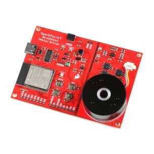
Sterownik, który umożliwia kontrolę dowolnego 3-fazowego silnika BLDC. Wyposażony został w wbudowaną łączność WiFi i Bluetooth oraz zintegrowany czujnik efektu Halla TMAG5273 i wzmacniacze czujników prądu INA240A1, dzieki czemu pozwala na wykrozystanie zaawansowanych algorytmów FOC. SparkFun ROB-22132
Płytka rozszerzeniowa ze sterownikiem silnika krokowego opartym na układzie STSPIN820. Idealnie nadaje się do użycia m.in. w drukarkach 2D/3D, robotach, kamerach. Pololu 2878
RoboClaw 2x160A Motor Controller to dwukanałowy sterownik silników prądu stałego (DC), napięcie pracy: 10,5..60V, maksymalny prąd ciągły: 120A, możliwość łatwej realizacji pętli sprzężenia zwrotnego z regulatorem PID, systemy bezpieczeństwa. Pololu 3582
Brak towaru
Moduł ze sterownikiem silnika krokowego oparty na układzie DRV8434A. Pozwala na zasilanie silnika bipolarnego prądem do 1,2 A na fazę i napięciem od 4,5 V do 48 V. Pololu 3765
Brak towaru
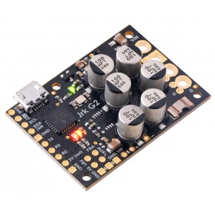
Pololu G2 18v15 High Power to miniaturowy sterownik silnika DC. Zasilanie sterownika: 6,5...30 V. Wydajność prądowa modułu: 15 A. Moduł posiada zabezpieczenie przed napięciem wstecznym i przepięciami. Pololu 1362
Kompaktowy sterownik silnika krokowego z układem TMC2208 o napięciu pracy od 4 do 35 V. Oferuje płynną, cichą pracę, wysoką wydajność, różnorodne tryby pracy oraz łatwą konfigurację. Jest sterowany przez interfejs STEP/DIR i stanowi idealne rozwiązanie dla drukarek 3D oraz podobnych zastosowań
Brak towaru
Pololu High-Power Motor Driver 24v23 CS