Produkty
Kategorie
- Kategorie główne
-
- ARDUINO
- AUTOMATYKA
- CYBERBEZPIECZEŃSTWO
- DRUK 3D
- EDUKACJA
- ELEKTRONIKA
- Akcesoria PC
- Chłodzenie
- Czujniki
- Czujniki 6DOF/9DOF/10DOF
- Czujniki ciśnienia
- Czujniki gazów
- Czujniki Halla
- Czujniki jakości cieczy
- Czujniki jakości powietrza
- Czujniki magnetyczne (kompasy)
- Czujniki medyczne
- Czujniki nacisku
- Czujniki odbiciowe
- Czujniki odległości
- Czujniki PH
- Czujniki podczerwieni
- Czujniki poziomu cieczy
- Czujniki położenia
- Czujniki prądu
- Czujniki przepływu
- Czujniki przyspieszenia (akcelerometry)
- Czujniki ruchu
- Czujniki światła i koloru
- Czujniki temperatury
- Czujniki wibracji
- Czujniki wilgotności gleby
- Czujniki wilgotności powietrza
- Żyroskopy
- Drukarki
- Elementy pasywne
- Gadżety
- GPS
- Inteligentne ubrania
- Kamery i akcesoria
- Karty pamięci i inne nośniki danych
- Komunikacja
- LED - diody, wyświetlacze, paski
- Materiały przewodzące
- Moduły elektroniczne
- Akcesoria JTAG
- Audio
- Czytniki kart pamięci
- Czytniki kodów paskowych
- Czytniki linii papilarnych
- Ekspandery linii I/O
- Enkodery
- Generatory DDS/PLL
- Klawiatury, przyciski
- Konwertery CAN
- Konwertery napięć
- Konwertery RS485
- Konwertery USB - I2C / 1-Wire / SPI
- Konwertery USB - UART / RS232
- Moduły HMI
- Moduły pamięci
- Moduły RTC
- Moduły z wyjściami mocy
- Moduły zasilające
- Obraz i wideo
- Odbiorniki podczerwieni TSOP
- Potencjometry cyfrowe
- Przetworniki A/C i C/A
- Rejestratory danych (data logger)
- Sterowniki LED
- Sterowniki serw
- Sterowniki silników
- Półprzewodniki
- Button
- Czujniki
- Czujniki dotykowe (Touch)
- Diody
- Energy harvesting
- Generatory PLL
- Inne
- Konwertery logiczne
- Liczniki energii
- Mikrokontrolery
- Mikroprocesory DSP
- Mostki prostownicze
- Optotriaki i transoptory
- Pamięci
- Przetworniki a/c (ADC)
- Przetworniki c/a (DAC)
- Sterowniki i mostki IGBT
- Sterowniki LED
- Sterowniki silników
- Syntezery DDS
- Timery
- Tranzystory
- Układy analogowe
- Układy audio
- Układy cyfrowe
- Układy interfejsowe
- Układy programowalne
- Układy RF
- Układy RTC
- Układy SoC
- Układy zasilające
- Układy zerujące
- Zabezpieczenia ESD
- Przekaźniki
- Przetworniki dźwięku
- Przewody
- Przewody świecące i akcesoria
- Przełączniki i przyciski
- Płytki prototypowe
- Wyświetlacze
- Złącza
- Adaptery USB PD do laptopów
- Gniazda do kart pamięci
- Gniazdka RJ-45
- Igły testowe (pogo pin)
- Konektory
- Podstawki
- Szybkozłącza
- Zworki
- Złącza ARK (Terminal Block)
- Złącza FFC / FPC ZIF
- Złącza goldpin
- Złącza IDC
- Złącza inne
- Złącza Jack
- Złącza JST
- Złącza koncentryczne (RF)
- Złącza krokodylkowe
- Złącza obrotowe
- Złącza szufladowe D-Sub
- Złącza USB
- Złącza zasilania DC
- Akcesoria PC
- KSIĄŻKI
- MECHANIKA
- MINIKOMPUTERY (SBC)
- PRZYRZĄDY POMIAROWE
- RASPBERRY PI
- Akcesoria do Raspberry Pi
- Chłodzenie do Raspberry Pi
- Kamery do Raspberry Pi
- Karty pamięci do Raspberry Pi
- Moduły rozszerzające do Raspberry Pi
- Obudowy do Raspberry Pi
- Prototypowanie Raspberry Pi
- Przewody audio-wideo do Raspberry Pi
- Raspberry Pi 3 model A+
- Raspberry Pi 3 model B
- Raspberry Pi 3 model B+
- Raspberry Pi 4 model B
- Raspberry Pi 400
- Raspberry Pi 5
- Raspberry Pi Compute Module
- Raspberry Pi model A/B+/2
- Raspberry Pi Pico
- Raspberry Pi Zero
- Raspberry Pi Zero 2 W
- Wyświetlacze do Raspberry Pi
- Zasilanie do Raspberry Pi
- WARSZTAT
- Chemia
- Elektronarzędzia
- Igły dozownicze
- Imadła
- Kleje i klejarki
- Listwy zasilające
- Lutowanie
- Akcesoria do lutowania
- Akcesoria SMD
- Chemia lutownicza
- Cyna
- Gąbki i czyściki
- Groty do lutownic
- Grzałki oraz kolby lutownicze
- Kulki BGA
- Laminaty
- Lutownice kolbowe
- Lutownice przenośne
- Maty i akcesoria antystatyczne (ESD)
- Myjki ultradźwiękowe
- Odsysacze do usuwania cyny
- Opalarki
- Pasty lutownicze
- Pędzle i szczotki ESD
- Plecionki do usuwania cyny
- Podgrzewacze
- Podstawki pod lutownice
- Silikonowe maty do lutowania
- Stacje lutownicze
- Tygle lutownicze
- Uchwyty, lupy
- Mikroskopy
- Miniwiertarki, miniszlifierki
- Narzędzia
- Noże i nożyczki
- Okulary ochronne
- Organizery
- Pęsety
- Plotery i Frezarki CNC
- Rurki termokurczliwe
- Ściągacze izolacji
- Taśmy
- Zaciskarki
- Zasilacze laboratoryjne
- Chemia
- WYCOFANE Z OFERTY
- WYPRZEDAŻ
- ZASILANIE
- ZESTAWY URUCHOMIENIOWE
- Atmel SAM
- Atmel Xplain
- AVR
- DFRobot FireBeetle
- ESP32
- ESP8266
- Feather / Thing Plus
- Freedom (Kinetis)
- Google Coral
- Inne zestawy uruchomieniowe
- M5Stack
- micro:bit
- Moduły peryferyjne
- Nordic nRF
- OPROGRAMOWANIE
- Particle Photon
- PIC
- Programatory Segger
- Programatory uniwersalne
- Raspberry Pi RP2040
- RFID
- RISC-V
- Seeed Studio LinkIt
- Sparkfun MicroMod
- STM32
- STM32 Discovery
- STM32 MP1
- STM32 Nucleo
- STM8
- Teensy
- WRTNode
- XIAO/Qt PY
- Atmel SAM
- ZESTAWY URUCHOMIENIOWE FPGA
- ARDUINO
Nowości
Nowości
31,41 zł Netto
Pololu - 2511
Wysyłka gratis
darmowa wysyłka na terenie Polski dla wszystkich zamówień powyżej 500 PLN
Wysyłka tego samego dnia
Jeśli Twoja wpłata zostanie zaksięgowana na naszym koncie do godz. 11:00
14 dni na zwrot
Każdy konsument może zwrócić zakupiony towar w ciągu 14 dni bez zbędnych pytań
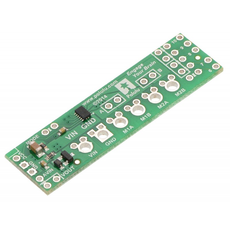
This small shield is an easy, economical way to control two small brushed DC motors with an Arduino or Arduino-compatible board. Its integrated DRV8835 dual motor driver allows it to operate from 1.5 V to 11 V, making it a great control option for low-voltage motors. The shield can deliver a continuous 1.2 A (1.5 A peak) per motor, or a continuous 2.4 A (3 A peak) to a single motor when configured with both channels connected in parallel.
DESCRIPTION
Overview
This motor driver shield and its corresponding Arduino library make it easy to control a pair of bidirectional, brushed DC motors with an Arduino or compatible board, such as the A-Star 32U4 Prime. The board features Texas Instruments’ DRV8835 dual H-bridge motor driver IC, which allows it to operate from 1.5 V to 11 V and makes it particularly well suited for driving small, low-voltage motors. The shield can deliver a continuous 1.2 A per channel and tolerate peak currents up to 1.5 A per channel for a few seconds, and the channels can be optionally configured to run in parallel to deliver twice the current to a single motor.
The shield ships fully populated with its SMD components, including the DRV8835 driver and a FET for reverse battery protection; header pins for interfacing with an Arduino and terminal blocks for connecting motors and power are included but are not soldered in (see the Assembly with included hardware section below).
The shield uses digital pins 7, 8, 9, and 10 for its control lines, though the control pin mappings can be customized if the defaults are not convenient. It should be compatible with any board that has a standard Arduino pin arrangement and the ability to generate PWM signals on pins 9 and 10. Compatible control boards include:
- A-Star 32U4 Prime
- Arduino Uno
- Arduino Leonardo
- Arduino Due
- Arduino Mega 2560
This shield is intended to provide a low-cost, basic motor driver option for Arduinos, so it is much smaller than typical Arduino shields and does not include pass-through, stackable headers. For higher-power drivers with more configuration options, see our larger MC33926 and VNH5019 motor driver shields.
For a higher-voltage alternative to this shield, please consider the A4990 dual motor driver shield. We also have a similar DRV8835 motor driver kit for the Raspberry Pi Model B+, as well as a smaller DRV8835 carrier (and an even smaller single-channel DRV8838 carrier) for those using a different controller or with tighter space constraints.
Features
- Dual-H-bridge motor driver: can drive two DC motors or one bipolar stepper motor
- Motor supply voltage: 1.5 V to 11 V
- Logic supply voltage 2 V to 7 V
- Output current: 1.2 A continuous (1.5 A peak) per motor
- Motor outputs can be paralleled to deliver 2.4 A continuous (3 A peak) to a single motor
- PWM operation up to 250 kHz (ultrasonic frequencies allow for quieter motor operation)
- Two possible interface modes: PHASE/ENABLE (default – one pin for direction, another for speed) or IN/IN (outputs mostly mirror inputs)
- Shield can optionally power the Arduino base directly when motor supply voltage is suitable
- Arduino library makes it easy to get started using this board as a motor driver shield
- Arduino pin mappings can be customized if the default mappings are not convenient
- Reverse-voltage protection on motor power supply
- Under-voltage lockout and protection against over-current and over-temperature
Assembly with included hardware
Before the shield can be plugged into your Arduino, header pins must be mounted to the bottom of the board (the side without any components or text) by soldering them into the appropriate holes. The shield ships with a 15-pin 0.1″ straight breakaway male header strip that can be broken into smaller pieces and used for this purpose. Four holes along the left side of the board (VCC, GND, GND, and AVIN) and all five holes along the right side of the board (digital pins 6 – 10) should be assembled with male header pins so that the shield will make the appropriate connections to the Arduino. Once assembled, one easy way to ensure that you are plugging the shield properly into the Arduino is to align the gap between pins 7 and 8 on the shield with the gap between pins 7 and 8 on the Arduino’s female headers.
If you want the option of powering the Arduino from the shield, you can solder two male header pins to the lower-left corner of the board (in the silkscreen box next to the VOUT label). These pins should point up, away from the Arduino. If you then place the included blue shorting block across these pins (as shown in the above assembled picture), reverse-protected shield power will power the Arduino through it’s VIN pin. See the Using the shield section below for more information on this, including some important warnings.
Three 2-pin, 5 mm terminal blocks are included for making easy motor and power connections to the shield once they have been slid together and soldered to the six large through-holes. Alternatively, you can solder 0.1″ male header pins to the smaller through-holes above the terminal block holes, or you can just solder wires directly to the shield.
Additional shorting blocks and header pins beyond what is included can be used to make some of the more advanced optional modifications to the shield, such as remapping the control pins or paralleling the outputs.
An Arduino is not included.
Using the shield
The shield plugs into Arduino digital pins 6, 7, 8, 9, and 10 on one side and Arduino VIN, GND, GND, and 5V/VCC on the other. The upper-left corner of the shield partially blocks the Arduino’s 3.3V pin, but this region of the board (marked with a white silkscreen box) can be removed if necessary to allow access. The shield also blocks Arduino digital pin 6, but it provides alternate access points to this pin via the neighboring through-holes. The board does not use pin 6 for anything.
In the shield's default state, the motor driver shield and Arduino are powered separately, though they share a common ground and the Arduino’s 5V rail serves as the shield’s logic supply. When used this way, the Arduino must be powered via USB, its power jack, or its VIN pin, and the shield must be supplied with 1.5 V to 11 V through its large VIN and GND pads. Attempting to power the shield from the Arduino is not recommended as this could result in large currents flowing through small traces. However, if the motor power supply is suitable, it is possible to power the Arduino from the shield. This can be accomplished by placing a jumper between the shield pins in the lower-left corner labeled VOUT and AVIN, which connects the reverse-protected motor supply voltage to the Arduino’s VIN pin to power the Arduino. The Arduino’s power jack must remain disconnected at all times in this configuration.
By default, the board operates in PHASE/ENABLE mode, in which a PWM signal applied to the ENABLE pin determines motor speed and the digital state of the PHASE pin determines direction of motor rotation. Arduino pins 9 and 7 are used to control the speed and direction, respectively, of motor 1, and pins 10 and 8 control the speed and direction of motor 2. The table below shows how the inputs affect the outputs in this mode:
Drive/brake operation in default PHASE/ENABLE mode | ||||
---|---|---|---|---|
xPHASE | xENABLE | MxA | MxB | operating mode |
0 | PWM | PWM | L | forward/brake at speed PWM % |
1 | PWM | L | PWM | reverse/brake at speed PWM % |
X | 0 | L | L | brake low (outputs shorted to ground) |
PHASE/ENABLE mode should be suitable for most applications.
Configuring the board for IN/IN mode
The operating mode of the driver is controlled by the MODE pin, which the shield connects to VCC by default to select PHASE/ENABLE mode. To change the mode, locate the pair of 0.1″ through-holes in the upper-left part of the board labeled “MODE” and use a knife to cut the trace that connects the two on the bottom side of the PCB. Since the MODE pin has an internal pull-down resistor, severing its connection to VCC is all it takes to switch the control interface to IN/IN, which allows for slightly more advanced control options as described in the table below:
Drive/coast or drive/brake operation with MODE=0 (IN/IN) | ||||
---|---|---|---|---|
xIN1 | xIN2 | MxA | MxB | operating mode |
0 | 0 | OPEN | OPEN | coast (outputs off) |
PWM | 0 | PWM | L | forward/coast at speed PWM % |
0 | PWM | L | PWM | reverse/coast at speed PWM % |
1 | PWM | PWM | L | forward/brake at speed 100% − PWM % |
PWM | 1 | L | PWM | reverse/brake at speed 100% − PWM % |
1 | 1 | L | L | brake low (outputs shorted to ground) |
Once the trace between the two pins has been cut, you can use a pair of header pins and a shorting block to control the mode: with the shorting block on, the mode is PHASE/ENABLE; with it off, the mode is IN/IN.
Configuring the board for single-channel mode (parallel outputs)
In order to use the two motor channels in parallel to control a single motor, it is important to ensure that both channels will always receive the same control signals, so the reconfiguration process begins with a modification to the control inputs. First, locate the 2×5 grouping of 0.1″ through-holes along the right side of the board. These holes run parallel to pins 6-10 and the traces between them on the underside of the PCB effectively link the Arduino pins to the DRV8835 control pins. If you want to remap one of these control pins, you can cut the desired trace with a knife and then run a wire from the inner hole to a new Arduino pin. The remapping for single-channel mode requires you cut one PWM (9 or 10) and one DIR (7 or 8) trace; cut 10 and 8 to control both outputs from the motor 1 input pins, or cut 9 and 7 to control both from the motor 2 input pins. If you then solder a row of header pins along the interior row of holes, you can safely connect both PWM lines together and both DIR lines together using shorting blocks. In this configuration, the two uncut Arduino control lines determine the behavior of both motor channels.
The last step is to connect the output channels together. An easy way to do this is to solder header pins to the two pairs of holes labeled “A” and “B” near the motor outputs. Placing shorting blocks across these pairs of pins connects M1A to M2A and M1B to M2B, which in turn means you can get up to 3 A from the connection points for either channel (e.g. you can have your motor connected just to the M1A and M1B terminal blocks rather than trying to find a way to connect it to all four motor outputs).
Real-world power dissipation considerations
The DRV8835 datasheet recommends a maximum continuous current of 1.5 A per motor channel. However, the chip by itself will overheat at lower currents. For example, in our tests at room temperature with no forced air flow, the chip was able to deliver 1.5 A per channel for approximately 15 seconds before the chip’s thermal protection kicked in and disabled the motor outputs, while a continuous current of 1.2 A per channel was sustainable for many minutes without triggering a thermal shutdown. The actual current you can deliver will depend on how well you can keep the motor driver cool. The carrier’s printed circuit board is designed to draw heat out of the motor driver chip, but performance can be improved by adding a heat sink. Our tests were conducted at 100% duty cycle; PWMing the motor will introduce additional heating proportional to the frequency.
Schematic diagram
TECHNICAL DETAILS
Dimensions
- Size: 2.0″ × 0.56″
(without included hardware) - Weight: 2.3 g
(without included hardware)
General specifications
- Motor driver: DRV8835
- Motor channels: 2
- Minimum operating voltage: 1.5 V
(the DRV8835 itself has a minimum motor supply voltage of 0 V, but the board's reverse-voltage protection circuit limits the minimum to 1.5 V) - Maximum operating voltage: 11 V
- Continuous output current per channel: 1.2 A
(typical results with 100% duty cycle at room temperature) - Peak output current per channel: 1.5 A
- Continuous paralleled output current: 2.4 A
(typical results with 100% duty cycle at room temperature) - Maximum PWM frequency: 250 kHz
- Reverse voltage protection?: Y
RESOURCES
File downloads
- Pololu DRV8835 Dual Motor Driver Shield for Arduino schematic diagram (214k pdf)
Printable schematic diagram for the Pololu DRV8835 Dual Motor Driver Shield for Arduino. - Texas Instruments DRV8835 motor driver datasheet (1MB pdf)
Recommended links
- Arduino library for the Pololu DRV8835 Dual Motor Driver Shield
This library for the Arduino makes it easy to interface with Pololu’s DRV8835 Dual Motor Driver Shield and drive a pair of brushed DC motors. It has been explicitly tested with the Uno R3, Leonardo, Mega 2560 R3, Due, and Duemilanove (ATmega328P). A sample sketch is included with the library. - Texas Instruments DRV8835 product page
Texas Instruments product page for the DRV8835, where you can find the latest datasheet and additional resources.
Produkty z tej samej kategorii (16)
Moduł zawiera dwa sterowniki silników L293D oraz rejestr przesuwny 74HC595. Rejestr przesuwny rozszerza 3 linie Arduino do 8 linii, co pozwala na sterowanie kierunkiem pracy silników. Wyjście L293D jest bezpośrednio sterowane wyjściami PWM Arduino
Shield z dwukanałowym sterownikiem silników DC dla Arduino. Ma napięcie pracy od 7 do 30 V i prąd ciągły do 1,2 A. Może być sterowany sygnałem PWM lub za pomocą wbudowanych przycisków. Cytron SHIELD-3AMOTOR
Sterownik silników prądu stałego, oparty na układzie L298. Zgodny z Arduino, napięcie zasilania silnika 4,8-35V, maksymalny prąd pobierany przez silnik 2A na kanał. SparkFun DEV-14129
Płytka rozszerzająca do trzech sterowników silników krokowych kompatybilna z Arduino Nano. Złącza sterownika krokowego pasują do modułów A4988
Rozszerzenie typu shield dla Arduino ze sterownikiem PWM 16-kanałowym, 12-bitowym pozwalającym na równoczesne sterowanie 16 serwomechanizmami za pomocą interfejsu I2C. Adafruit 1411
Brak towaru
Gravity: IO Expansion & Motor Driver Shield to płytka rozszerzeń kompatybilna z Arduino, która udostępnia cyfrowe porty I/O, piny analogowe interfejsy I2C, SPI i UART, a także sterownik silników DC. DFRobot DFR0502
Sterownik silników DC, który pozwala na kontrolowanie ruchu trzech napędów za pomocą interfejsu I2C. W zestawie płytka bez złączy. Pololu 5032
Brak towaru
Sterownik silników DC, który pozwala na kontrolowanie ruchu dwóch napędów za pomocą interfejsu I2C. Płytka z przylutowanymi złączami. Pololu 5039
Brak towaru
Sterownik silników DC, który pozwala na kontrolowanie ruchu dwóch napędów za pomocą interfejsu I2C. Płytka ze złączami do montażu. Pololu 5040
Brak towaru
Dwukanałowy (mostek H) sterownik silników z układem L298, zgodny z Arduino, napięcie zasilania silnika 4,8-35VDC/2A. Może sterować jednym lub dwoma silnikami DC lub jednym silnkiem krokowym z możliwością użycia hamulca elektronicznego. DFRobot DRI0009
Sterownik silników DC, który pozwala na kontrolowanie ruchu trzech napędów za pomocą interfejsu I2C. W zestawie płytka z przylutowanymi złączami. Pololu 5068
Sterownik silników DC, który pozwala na kontrolowanie ruchu trzech napędów za pomocą interfejsu I2C. W zestawie płytka ze złączami do montażu. Pololu 5069
Moduł z 2-kanałowym sterownikiem silników DC do płytek Arduino. Pozwala na sterowanie napędami o napięciu zasilania od 6 do 32 V i poborze prądu do 0,65 A. Pololu 2512
Sterownik silników DC, który pozwala na kontrolowanie ruchu trzech napędów za pomocą interfejsu I2C. W zestawie płytka bez złączy. Pololu 5070
Sterownik silników dla Arduino który w prosty sposób pozwala sterować silnikami DC dużej mocy. Do 12 A na kanał dla pracy ciągłej. Pololu 2507
Brak towaru
Moduł sterownika silnika bezszczotkowego SimpleFOC dedykowany do płytek Arduino. SimpleFOC Shield v2.0.4
Brak towaru