


zł33.57 tax excl.
Pololu - 2511
This small shield is an easy, economical way to control two small brushed DC motors with an Arduino or Arduino-compatible board. Its integrated DRV8835 dual motor driver allows it to operate from 1.5 V to 11 V, making it a great control option for low-voltage motors. The shield can deliver a continuous 1.2 A (1.5 A peak) per motor, or a continuous 2.4 A (3 A peak) to a single motor when configured with both channels connected in parallel.
DESCRIPTION
Overview
This motor driver shield and its corresponding Arduino library make it easy to control a pair of bidirectional, brushed DC motors with an Arduino or compatible board, such as the A-Star 32U4 Prime. The board features Texas Instruments’ DRV8835 dual H-bridge motor driver IC, which allows it to operate from 1.5 V to 11 V and makes it particularly well suited for driving small, low-voltage motors. The shield can deliver a continuous 1.2 A per channel and tolerate peak currents up to 1.5 A per channel for a few seconds, and the channels can be optionally configured to run in parallel to deliver twice the current to a single motor.
The shield ships fully populated with its SMD components, including the DRV8835 driver and a FET for reverse battery protection; header pins for interfacing with an Arduino and terminal blocks for connecting motors and power are included but are not soldered in (see the Assembly with included hardware section below).
The shield uses digital pins 7, 8, 9, and 10 for its control lines, though the control pin mappings can be customized if the defaults are not convenient. It should be compatible with any board that has a standard Arduino pin arrangement and the ability to generate PWM signals on pins 9 and 10. Compatible control boards include:
This shield is intended to provide a low-cost, basic motor driver option for Arduinos, so it is much smaller than typical Arduino shields and does not include pass-through, stackable headers. For higher-power drivers with more configuration options, see our larger MC33926 and VNH5019 motor driver shields.
For a higher-voltage alternative to this shield, please consider the A4990 dual motor driver shield. We also have a similar DRV8835 motor driver kit for the Raspberry Pi Model B+, as well as a smaller DRV8835 carrier (and an even smaller single-channel DRV8838 carrier) for those using a different controller or with tighter space constraints.
Features
Assembly with included hardware
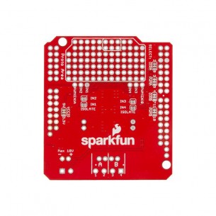
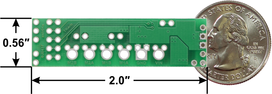
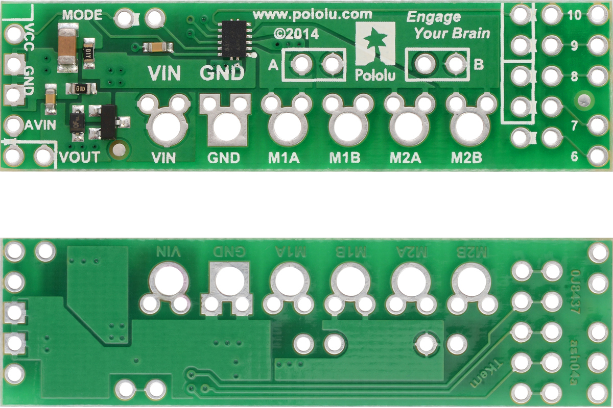
Before the shield can be plugged into your Arduino, header pins must be mounted to the bottom of the board (the side without any components or text) by soldering them into the appropriate holes. The shield ships with a 15-pin 0.1″ straight breakaway male header strip that can be broken into smaller pieces and used for this purpose. Four holes along the left side of the board (VCC, GND, GND, and AVIN) and all five holes along the right side of the board (digital pins 6 – 10) should be assembled with male header pins so that the shield will make the appropriate connections to the Arduino. Once assembled, one easy way to ensure that you are plugging the shield properly into the Arduino is to align the gap between pins 7 and 8 on the shield with the gap between pins 7 and 8 on the Arduino’s female headers.
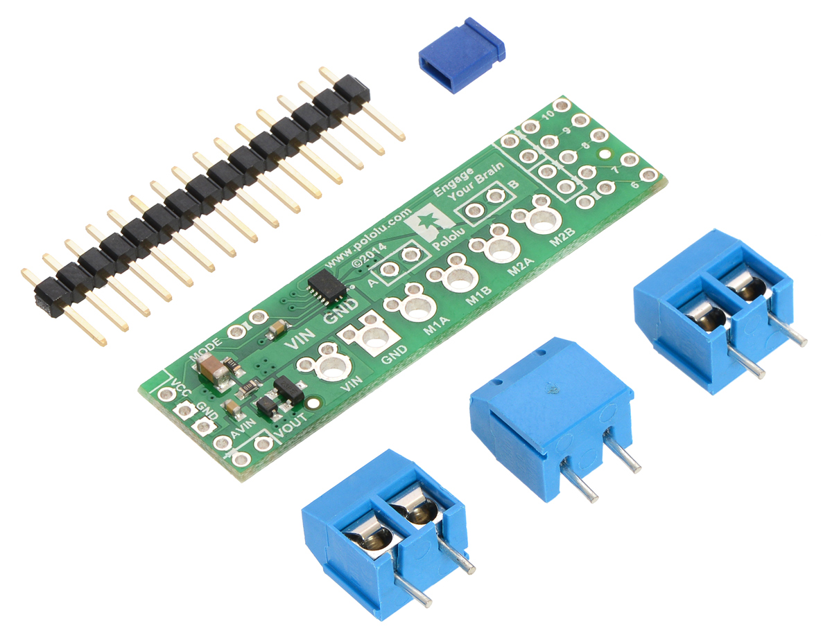
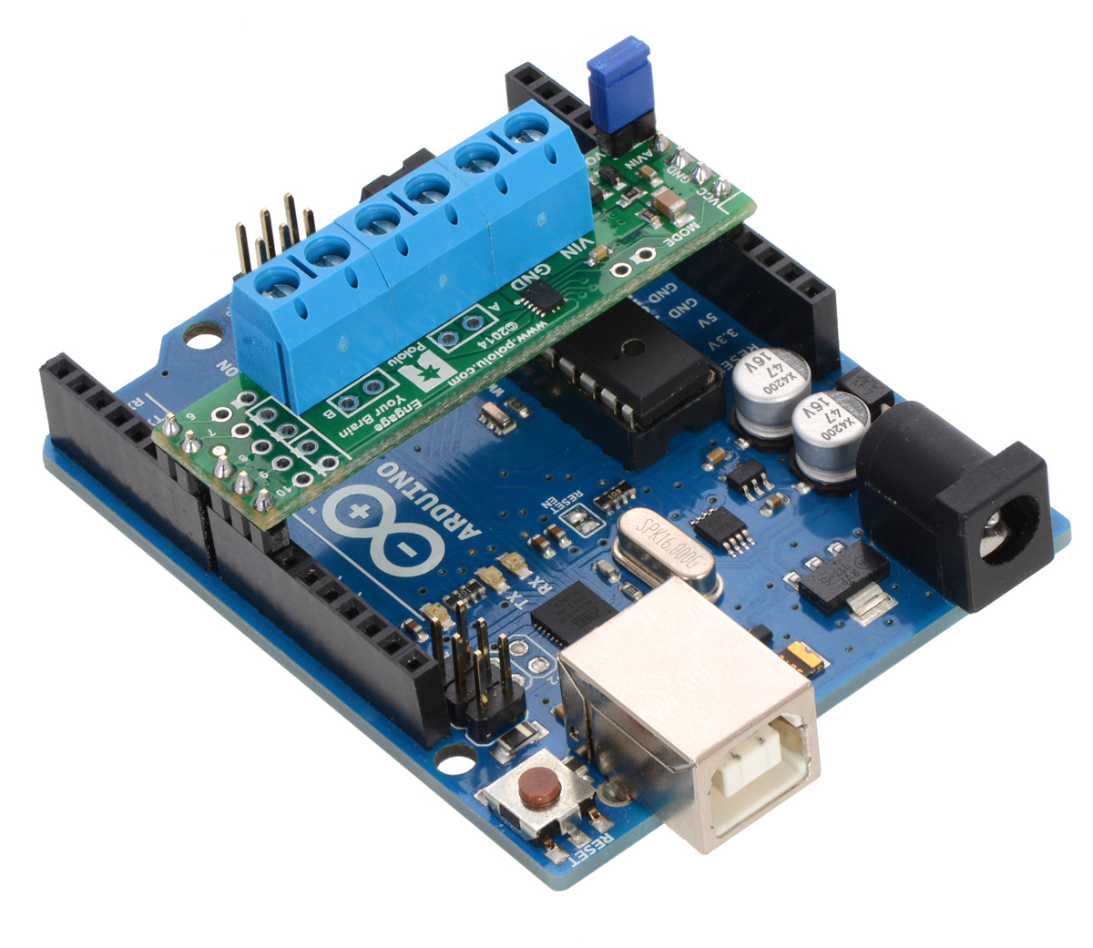
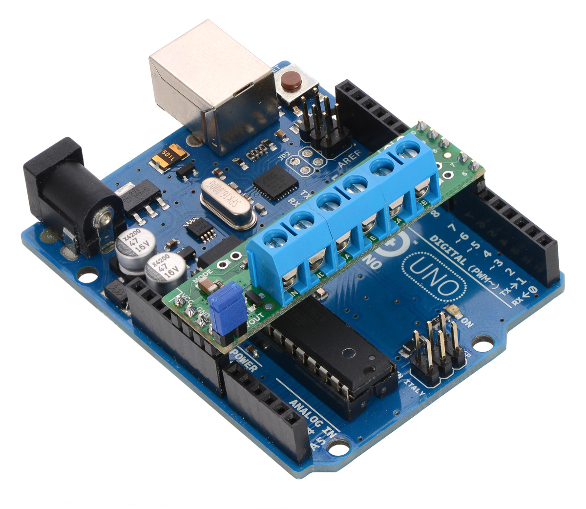
If you want the option of powering the Arduino from the shield, you can solder two male header pins to the lower-left corner of the board (in the silkscreen box next to the VOUT label). These pins should point up, away from the Arduino. If you then place the included blue shorting block across these pins (as shown in the above assembled picture), reverse-protected shield power will power the Arduino through it’s VIN pin. See the Using the shield section below for more information on this, including some important warnings.
Three 2-pin, 5 mm terminal blocks are included for making easy motor and power connections to the shield once they have been slid together and soldered to the six large through-holes. Alternatively, you can solder 0.1″ male header pins to the smaller through-holes above the terminal block holes, or you can just solder wires directly to the shield.
Additional shorting blocks and header pins beyond what is included can be used to make some of the more advanced optional modifications to the shield, such as remapping the control pins or paralleling the outputs.
An Arduino is not included.
Using the shield
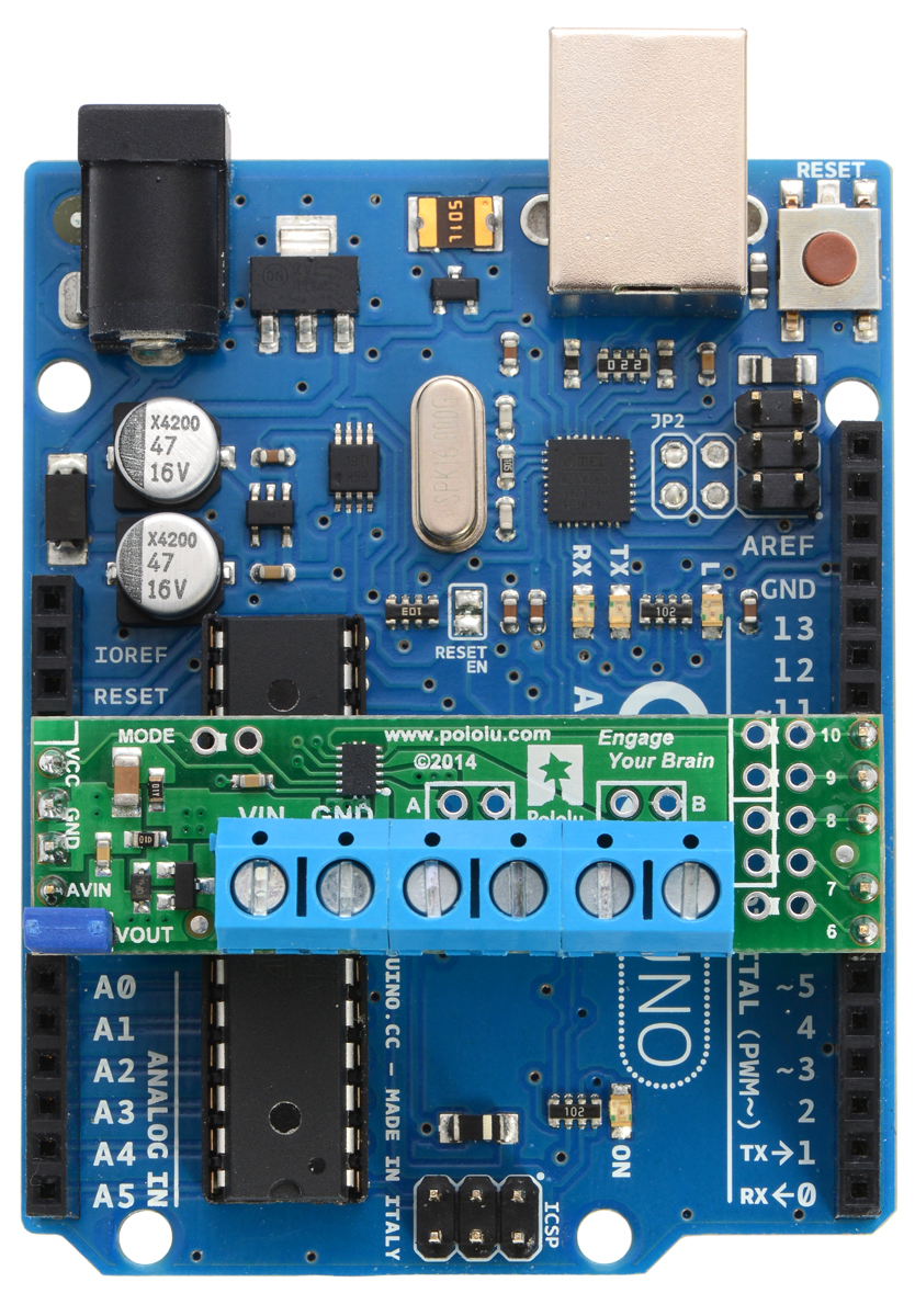
The shield plugs into Arduino digital pins 6, 7, 8, 9, and 10 on one side and Arduino VIN, GND, GND, and 5V/VCC on the other. The upper-left corner of the shield partially blocks the Arduino’s 3.3V pin, but this region of the board (marked with a white silkscreen box) can be removed if necessary to allow access. The shield also blocks Arduino digital pin 6, but it provides alternate access points to this pin via the neighboring through-holes. The board does not use pin 6 for anything.
In the shields default state, the motor driver shield and Arduino are powered separately, though they share a common ground and the Arduino’s 5V rail serves as the shield’s logic supply. When used this way, the Arduino must be powered via USB, its power jack, or its VIN pin, and the shield must be supplied with 1.5 V to 11 V through its large VIN and GND pads. Attempting to power the shield from the Arduino is not recommended as this could result in large currents flowing through small traces. However, if the motor power supply is suitable, it is possible to power the Arduino from the shield. This can be accomplished by placing a jumper between the shield pins in the lower-left corner labeled VOUT and AVIN, which connects the reverse-protected motor supply voltage to the Arduino’s VIN pin to power the Arduino. The Arduino’s power jack must remain disconnected at all times in this configuration.
By default, the board operates in PHASE/ENABLE mode, in which a PWM signal applied to the ENABLE pin determines motor speed and the digital state of the PHASE pin determines direction of motor rotation. Arduino pins 9 and 7 are used to control the speed and direction, respectively, of motor 1, and pins 10 and 8 control the speed and direction of motor 2. The table below shows how the inputs affect the outputs in this mode:
| Drive/brake operation in default PHASE/ENABLE mode | ||||
|---|---|---|---|---|
| xPHASE | xENABLE | MxA | MxB | operating mode |
| 0 | PWM | PWM | L | forward/brake at speed PWM % |
| 1 | PWM | L | PWM | reverse/brake at speed PWM % |
| X | 0 | L | L | brake low (outputs shorted to ground) |
PHASE/ENABLE mode should be suitable for most applications.
Configuring the board for IN/IN mode
The operating mode of the driver is controlled by the MODE pin, which the shield connects to VCC by default to select PHASE/ENABLE mode. To change the mode, locate the pair of 0.1″ through-holes in the upper-left part of the board labeled “MODE” and use a knife to cut the trace that connects the two on the bottom side of the PCB. Since the MODE pin has an internal pull-down resistor, severing its connection to VCC is all it takes to switch the control interface to IN/IN, which allows for slightly more advanced control options as described in the table below:
| Drive/coast or drive/brake operation with MODE=0 (IN/IN) | ||||
|---|---|---|---|---|
| xIN1 | xIN2 | MxA | MxB | operating mode |
| 0 | 0 | OPEN | OPEN | coast (outputs off) |
| PWM | 0 | PWM | L | forward/coast at speed PWM % |
| 0 | PWM | L | PWM | reverse/coast at speed PWM % |
| 1 | PWM | PWM | L | forward/brake at speed 100% − PWM % |
| PWM | 1 | L | PWM | reverse/brake at speed 100% − PWM % |
| 1 | 1 | L | L | brake low (outputs shorted to ground) |
Once the trace between the two pins has been cut, you can use a pair of header pins and a shorting block to control the mode: with the shorting block on, the mode is PHASE/ENABLE; with it off, the mode is IN/IN.
Configuring the board for single-channel mode (parallel outputs)
In order to use the two motor channels in parallel to control a single motor, it is important to ensure that both channels will always receive the same control signals, so the reconfiguration process begins with a modification to the control inputs. First, locate the 2×5 grouping of 0.1″ through-holes along the right side of the board. These holes run parallel to pins 6-10 and the traces between them on the underside of the PCB effectively link the Arduino pins to the DRV8835 control pins. If you want to remap one of these control pins, you can cut the desired trace with a knife and then run a wire from the inner hole to a new Arduino pin. The remapping for single-channel mode requires you cut one PWM (9 or 10) and one DIR (7 or 8) trace; cut 10 and 8 to control both outputs from the motor 1 input pins, or cut 9 and 7 to control both from the motor 2 input pins. If you then solder a row of header pins along the interior row of holes, you can safely connect both PWM lines together and both DIR lines together using shorting blocks. In this configuration, the two uncut Arduino control lines determine the behavior of both motor channels.
The last step is to connect the output channels together. An easy way to do this is to solder header pins to the two pairs of holes labeled “A” and “B” near the motor outputs. Placing shorting blocks across these pairs of pins connects M1A to M2A and M1B to M2B, which in turn means you can get up to 3 A from the connection points for either channel (e.g. you can have your motor connected just to the M1A and M1B terminal blocks rather than trying to find a way to connect it to all four motor outputs).
Real-world power dissipation considerations
The DRV8835 datasheet recommends a maximum continuous current of 1.5 A per motor channel. However, the chip by itself will overheat at lower currents. For example, in our tests at room temperature with no forced air flow, the chip was able to deliver 1.5 A per channel for approximately 15 seconds before the chip’s thermal protection kicked in and disabled the motor outputs, while a continuous current of 1.2 A per channel was sustainable for many minutes without triggering a thermal shutdown. The actual current you can deliver will depend on how well you can keep the motor driver cool. The carrier’s printed circuit board is designed to draw heat out of the motor driver chip, but performance can be improved by adding a heat sink. Our tests were conducted at 100% duty cycle; PWMing the motor will introduce additional heating proportional to the frequency.
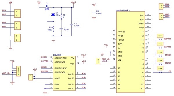
Schematic diagram
TECHNICAL DETAILS
Dimensions
General specifications
RESOURCES
File downloads
Recommended links
Data sheet
Manufacturer BTC Korporacja sp. z o. o. Lwowska 5 05-120 Legionowo Poland sprzedaz@kamami.pl 22 767 36 20
Responsible person BTC Korporacja sp. z o. o. Lwowska 5 05-120 Legionowo Poland sprzedaz@kamami.pl 22 767 36 20
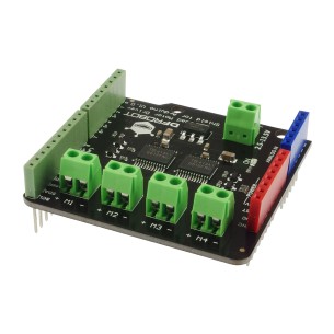
Quad DC Motor Driver Shield is an Arduino compatible DC motor driver that allows you to control 4 DC motors with a voltage between 2.5 ... 13.5V and up to 1.2A. DFRobot DRI0039
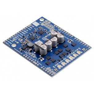
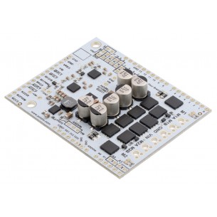
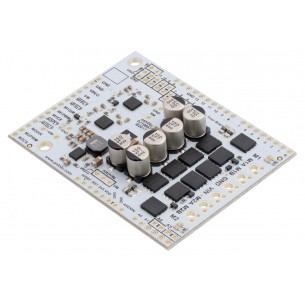
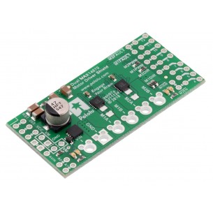
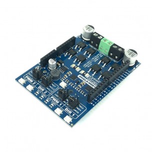
This shield makes it easy to control two high-power DC motors with your Arduino or Arduino-compatible board. Its twin discrete MOSFET H-bridges support a wide 6.5 V to 30 V operating range and are efficient enough to deliver a continuous 18 A without a heat sink.
Pololu Dual G2 High-Power Motor Driver 24v18 is an extension that allows you to control two DC motors designed for Arduino tiles. The motor can be supplied with 6.5 ... 40V voltage and can draw a maximum current of 18A. Pololu 2518
No product available!
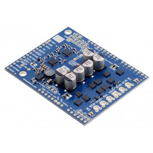
Pololu Dual G2 High-Power Motor Driver 18v22 is an extension that allows you to control two DC motors designed for Arduino tiles. The motor can be supplied with 6.5 ... 30V voltage and can draw up a maximum current of 22A. Polol 2517
No product available!
DRV8825 Stepper Motor Driver Module for Arduino. It allows you to control two drives, equipped with an XBee connector. DFRobot DRI0023
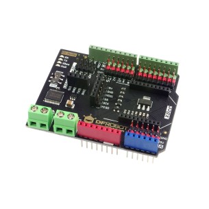
Gravity: IO Expansion & Motor Driver Shield is an Arduino compatible expansion board that provides digital I / O ports, analog I2C, SPI and UART interfaces, as well as a DC motor driver. DFRobot DFR0502
Dual MAX14870 Motor Driver is a dual DC motor controller compatible with the Arduino standard that allows you to control two DC motors with 4.5 ... 36V continuous current of 1.7A. Polol 2519
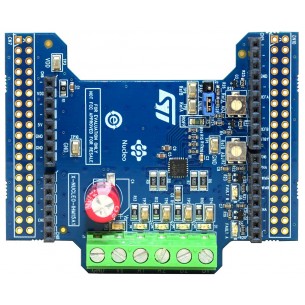
The X-NUCLEO-IHM15A1 dual brush DC motor driver expansion board is based on the STSPIN840 for STM32 Nucleo. It provides an affordable and easy-to-use solution for the implementation of compact motor driving applications such as thermal printers, robotics and toys
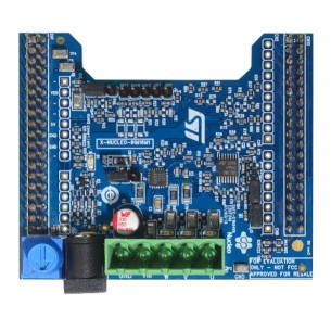
The X-NUCLEO-IHM16M1 motor driver expansion board is based on the STSPIN830 monolithic driver for three-phase brushless motors. It represents an affordable, easy-to-use solution for driving brushless motors in your STM32 Nucleo project, implementing single and three-shunt current sensing
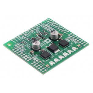
Dual DC motor controller designed for Arduino, which enables the motor to be supplied with voltage in the 4.5 ... 28V range and power consumption in continuous operation of 2.6 A (5A at the top) of two DC motors. Polol 2520
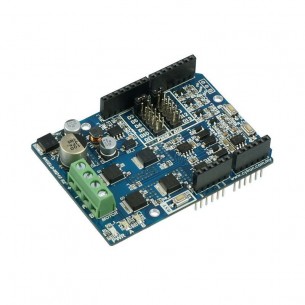
Shield with dual-channel DC motor driver for Arduino. It has an operating voltage from 7 to 30 V and a continuous current of up to 10 A. It can be controlled by a PWM signal or by means of built-in buttons. Cytron SHIELD-MDD10
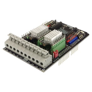
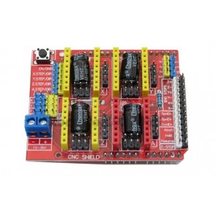
Extension module for building a 3D printer or CNC machine compatible with Arduino. The kit includes four A4988 stepper motor drivers. the module is supplied with the voltage from 12 to 36 V
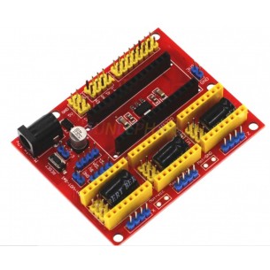
Expansion board for three stepper motor drivers compatible with Arduino Nano. The stepper driver connectors fit A4988 modules
No product available!
Shield with DC motor driver for Arduino. It has an operating voltage of 7 to 30 V and a maximum continuous current of 10 A. It can be controlled by a PWM signal or by means of built-in buttons. Cytron SHIELD-MD10
Pololu - 2511