
- Obecnie brak na stanie
")

")

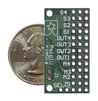
Pololu RC Servo Multiplexer 4 Channel (assembled)
Pololu RC Servo Multiplexer 4 Channel (assembled)
This compact device serves as a four-channel multiplexer of hobby radio control pulses, allowing easy switching between two independent signal sources. A fifth channel selects whether the output is from the master or the slave source: a pulse width below the threshold selects the master channels, while a longer pulse width selects the slave channels. This version comes with header pins soldered in.
 |
The Pololu RC servo multiplexer can be used with standard hobby radio control systems and servo controllers to allow easy switching of servo control between two independent sources using a fifth channel as the output selector. This makes it ideal for applications in which you have two possible control sources and want to be able to switch between them on the fly. For example, you could connect two RC receivers to the same set of servos (or similar devices, such as RC-based motor controllers) and allow the master transmitter to decide whether the master or slave transmitter is in control, thereby setting up your own buddy-system training setup. Another possible application would involve multiplexing between an RC receiver and a servo controller, which would allow you to switch between autonomous and manual control of a set of servos.
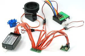 |
The pins on the multiplexer allow for easy connecting to servo cables: the column along the outside edge of the board is ground, the column in the middle is power (which must be supplied by the master), and the interior column is the signal. The pin spacing is 0.100". This multiplexer is available as an assembled version with male header pins soldered in or as a partial kit. The male headers can be used with standard servo connectors; the kit provides additional flexibility and compactness by allowing wires to be soldered directly to the board, as shown in the picture to the right. The kit version ships with three 13×1 male header strips, a 2×1 male header strip, and a blue shorting block.
The power supplied by the master should be between 2.5 and 15 V, and it must be capable of supplying the current that the servos connected to the outputs draw. The logic voltage used on the multiplexer board will be regulated to 5 V if the supply voltage is greater than 5 V; otherwise, it will be approximately equal to the supply voltage. Note that the master and slave signal voltages must not exceed this logic voltage.
Pins S1 through S4 comprise the four slave input signals and pins M1 through M4 comprise the four master input signals. Pins OUT1 through OUT4 are the multiplexed outputs, and their source is determined by the signal on the SEL pin. If the selection pulse width is below the 1.6 ms threshold, OUT1 through OUT4 output the signals on M1 through M4, respectively (i.e. the master source is output); otherwise, OUT1 through OUT4 output the signals on S1 through S4, respectively (i.e. the slave source is output). Note that there is approximately ±0.1 ms of hysteresis on the threshold, meaning that the pulse width will have to get to approximately 1.7 ms before the slave signals become the output, and once this happens, the signal will have to fall below 1.5 ms before the master signals become the output.
If the selection signal is invalid, an optional jumper across the pins labeled J1 determines the output behavior. If the jumper is left off, the output channels go low and stay low for as long as the signal on the SEL pin remains invalid. For many servos and electronic speed controls (ESCs), a constant low on the signal line will turn them off, which might be desirable if the control signals are known to be bad. If the jumper is in place, the output channels default to the master signals if the selection signal becomes invalid. The multiplexer considers a valid RC signal to have a 10 – 100 Hz pulse rate and a 0.5 – 2.5 ms pulse width.
The board has three indicator LEDs. If the outputs come from the master, only the green LED will be lit; if the outputs come from the slave, the yellow LED will be lit; if the outputs are turned off (all low) because of an invalid selector signal, the red and green LEDs will be lit.
Producent BTC Korporacja sp. z o. o. Lwowska 5 05-120 Legionowo Polska sprzedaz@kamami.pl 22 767 36 20
Osoba odpowiedzialna BTC Korporacja sp. z o. o. Lwowska 5 05-120 Legionowo Polska sprzedaz@kamami.pl 22 767 36 20
Brak towaru
Brak towaru
ZESTAW STARTOWY - REZYSTORY E3 - 800szt.
Brak towaru
Brak towaru
Brak towaru
Brak towaru
Brak towaru
Brak towaru
Brak towaru
Brak towaru
Brak towaru
Generator/szukacz sygnału audio - zestaw do samodzielnego montażu
Brak towaru
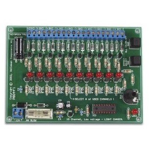
10-kanałowy generator efektów świetlnych - zestaw do samodzielnego montażu
Brak towaru
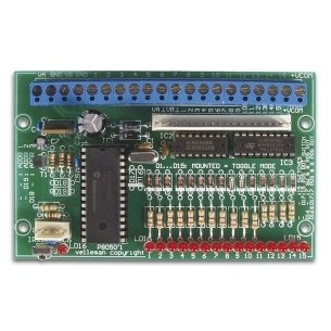
15 kanałowy odbiornik podczerwieni - zestaw do samodzielnego montażu
Brak towaru
15-kanałowy nadajnik podczerwieni - zestaw do samodzielnego montażu
Brak towaru
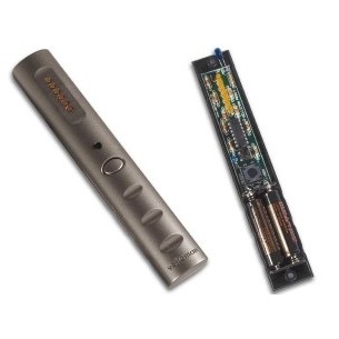
15-kanałowy pilot zdalnego sterowania - zestaw do samodzielnego montażu
Brak towaru
Pololu RC Servo Multiplexer 4 Channel (assembled)