- Obecnie brak na stanie

LSM303DLM Kompas 3D i akcelerometr ze stabilizatorami napięcia
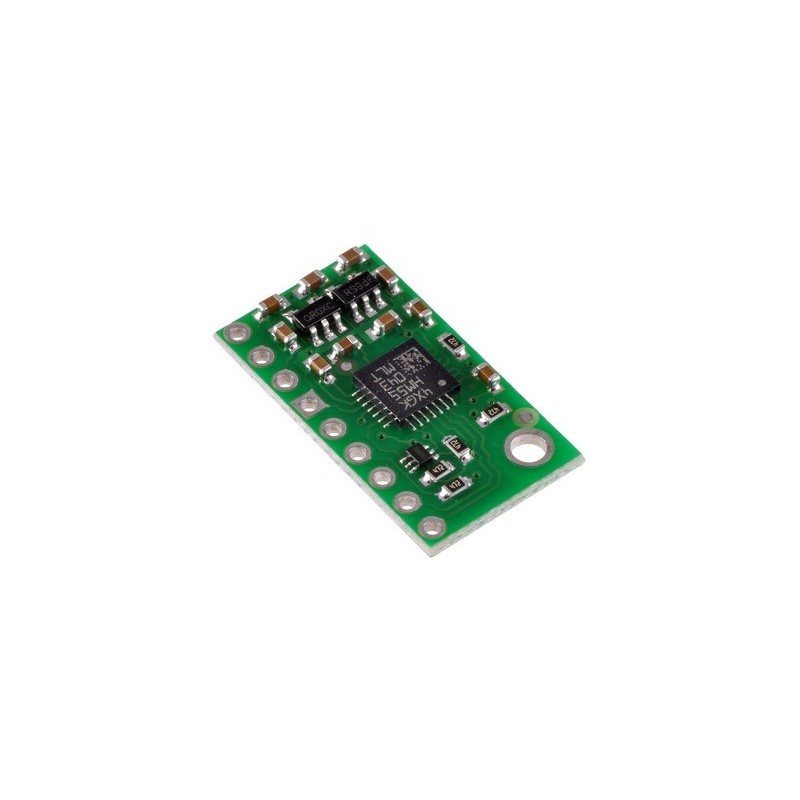
LSM303DLM łączy w sobie funkcjonalność cyfrowego, 3-osiowego akcelerometru oraz 3-osiowego magnetometru, które to połączenie jest wręcz stworzone do budowy kompasu z kompensacją odchylenia. Sześć niezależnych odczytów, których czułość może być ustawiona w zakresach ±2 do ±8 g i ±1.3 do ±8.1 gauss, jest dostępnych przez interfejs I2C. Płytka zawiera stabilizatory napięcia i pozwala na operowanie napięciem rzędu 2,6 do 5,5 V, a standardowe wyprowadzenia w rastrze 2,54mm (pasuje do tzw. goldpinów) ułatwia wykorzystanie jej ze standardowymi płytkami uniwersalnymi i prototypowymi.
 |
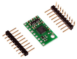
LSM303DLM to dobry układ, ale jego małe wymiary sprawiają, że jego wykorzystanie może sprawić hobbyście kłopoty. Urządzenie wymaga także dwóch różnych napięć zasilania, które zwykle nie występują w jednym układzie. Sprzedawana przez nas płytka rozwiązuje te problemy, przez zastosowanie dodatkowych elementów, takich jak 2 stabilizatory napięcia i obwód zmiany poziomów napięć, jednocześnie zachowując minimalne wymiary. Płytka jest przez nas dostarczana w pełni polutowana, od razu gotowa do użycia - jak na zdjęciu.
LSM303 posiada wiele konfigurowalnych opcji, wliczając w to dynamicznie wybierane zakresy/czułości dla akcelerometra i magnetometru, szybkość transferu danych i dwa niezależnie-programowalne zewnętrzne przerwania (wykorzystujące dwa piny).Magnetometr oraz akcelerometr, mogą być niezależnie włączane lub wyłączane, aby oszczędzać energię, a specjalne funkcja pozwala wybudzić i uśpić akcelerometr za pomocą zewnętrznego przerwania. 6 niezależnych odczytów z magnetometru i akcelerometru (czasami nazywane 6DoF) jest dostępnych przez magistralę I2C/TWI. Interfejs ten może być z powodzeniem wykorzystany w wielu aplikacjach, wliczając w to kompas z kompensacją odchylenia, który może zostać wykorzystany do określenia kierunków niezależnie od ustawienia płytki.
Płytka zawiera dwa stabilizatory, które dostarczają napięcia 1,8V i 3V, niezbędne do prawidłowej pracy układu LSM303. Umożliwia to zasilenie z tylko jednego źródła napięcia 2,6 ÷ 5,5V. Napięcia ze stabilizatorów są różwnież wyprowadzone na piny płytki i mogą dostarczyć dodatkowym peryferiom aż do 150mA dla 1,8V i 300mA dla 3V. Płytka zwiera również specjalny obwód, który umożliwia dopasowanie napięć linii danych do poziomu napięcia dostarczanego do VIN, co znacznie ułatwia integrację modułu z systemami zasilanymi z 3,3V lub 5V.
 |
Przynajmniej 4 połączenia są wymagane do obsługi LSM303DLM: VIN, GND, SCL i SDA. VIN powinno być połączone do 2,6 ÷ 5,5 V, GND do 0 V, a SCL i SDA do magistrali I2C dopasowanej poziomami logicznymi do VIN.
|
|
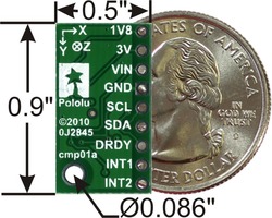
| PIN | Opis |
|---|---|
| VIN | To jest główny pin zasilania modułu. Wymagane napięcie to 2,6 ÷ 5,5 V. Napięcia poziomów linii SCL i SDA są dopasowywane do tego napięcia. |
| GND | Masa (0 V) wymagana przy podłączaniu zasilania. Masa powinna być wspólna dla modułu, jak i dla układu, który będzie tym modułem stertować. |
| 1V8 | Wyjście stabilizatora 1,8V. Umożliwia dodatkowym peryferiom pobór prądu aż do 150mA. |
| 3V | Wyjście stabilizatora 3V. Umożliwia dodatkowym peryferiom pobór prądu aż do 300mA. |
| SCL | Linia I2C: stan wysoki jest równy VIN, a niski 0 V |
| SDA | Linia I2C: stan wysoki jest równy VIN, a niski 0 V |
| DRDY | Wskaźnik gotowości danych do odczytu, dla magnetometru. Poziom logiczny 1,8V. Stan wysoki oznacza, że dane z magnetometru są gotowe do odczytu. |
| INT1 | Przerwanie 1 - 1,8V-stan-logiczny |
| INT2 | Przerwanie 2 - 1,8V-stan-logiczny |
 |
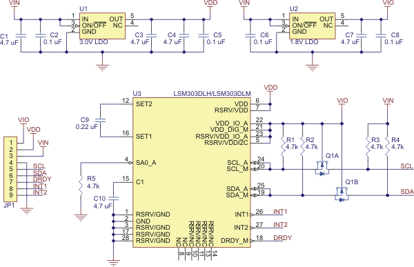
The above schematic shows the additional components the carrier board incorporates to make the LSM303 easier to use, including the voltage regulators that allow the board to be powered from a single 2.6 – 5.5 V supply and the level-shifter circuit that allows for I˛C communication at the same logic voltage level as VIN.
The LSM303DLM readings can be queried and the device can be configured through the I˛C bus. The module acts as two chained I˛C slave devices, with the accelerometer and magnetometer clock and data lines tied together to the same I˛C bus to ease communication. Additionally, level shifters on the I˛C clock (SCL) and data lines (SDA) enable I˛C communication with microcontrollers operating at the same voltage as VIN (2.6 – 5.5V). A detailed explanation of the protocol can be found in the LSM303DLM datasheet (519k pdf), and more detailed information about I˛C in general can be found in NXP’s I˛C-bus specification (371k pdf).
The accelerometer and the magnetometer have separate 7-bit slave addresses on the I˛C bus. The magnetometer’s slave address is 0011110b and cannot be changed. The accelerometer’s slave address has its least significant bit (LSb) determined by the voltage on the slave address selector pad (SA0_A). The carrier board pulls SA0_A to ground through a 4.7kΩ resistor, setting the accelerometer’s slave address to 0011000b by default. If the accelerometer’s selected slave address happens to conflict with some other device on your I˛C bus, it is possible to access SA0_A through the untented via on the bottom of the board and pull it up.
In our tests of the board, we were able to communicate with the chip at clock frequencies up to 400 kHz; higher frequencies might work but were not tested. The chip itself and carrier board do not meet of some requirements to make the device compliant with I˛C fast-mode. It is missing 50ns spike suppression on the clock and data lines, and additional pull-ups on the clock and data lines might also be necessary to achieve compliant signal timing characteristics.
The datasheet provides all the information you need to use this sensor, but picking out the important details can take some time. Here are some pointers for communicating with and configuring the LSM303DLM that we hope will get you up and running a little bit faster:
The inertial interrupts (INT1 and INT2) are highly configurable 1.8V-level outputs that can change due to accelerations (the magnetometer has no effect on INT1 or INT2). If the sleep-to-wakeup feature of the accelerometer is enabled, when an interrupt is triggered, the accelerometer wakes up.
 |
MinIMU-9 Gyro, Accelerometer, and Compass (L3G4200D and LSM303DLM Carrier) |
 |
66-Channel LS20031 GPS Receiver Module |
 |
0.100" (2.54 mm) Breakaway Male Header: 1x40-Pin, Straight |
Producent BTC Korporacja sp. z o. o. Lwowska 5 05-120 Legionowo Polska sprzedaz@kamami.pl 22 767 36 20
Osoba odpowiedzialna BTC Korporacja sp. z o. o. Lwowska 5 05-120 Legionowo Polska sprzedaz@kamami.pl 22 767 36 20
Zestaw ESP32-P4-NANO-KIT-D to kompletna platforma do projektowania systemów HMI i IoT. Oferuje wysoką wydajność, bogaty zestaw interfejsów oraz obsługę Wi-Fi 6 i Bluetooth 5. W zestawie znajduje się m.in. ekran dotykowy 10.1", kamera i głośnik, co umożliwia szybkie prototypowanie urządzeń interaktywnych.
Brak towaru
Brak towaru
Komputer jednopłytkowy z mikrokontrolerem STM32F417VGT6 (ARM Cortex-M4, 1024 kB Flash, 192 kB RAM, LQFP100)
Brak towaru
Brak towaru
Brak towaru
Wyświetlacz OLED alfanumeryczny 2x16, 80x36 mm, negatyw (czarne tło), żółte piksele, 5V, RoHS
Brak towaru
TUYA V3 to kompaktowe, czarne gniazdko Wi-Fi z funkcją pomiaru zużycia energii, obsługą harmonogramów i zdalnym sterowaniem przez aplikację mobilną. Przystosowane do obciążeń do 3600 W, sprawdzi się w codziennej automatyzacji urządzeń domowych oraz w systemach smart home.
Brak towaru
Magnes trwały neodymowy walcowy o średnicy 15 mm i wysokości 2 mm.
Brak towaru
Prototypowa płytka stykowa 270 punktów o wielkości 82x46x1 mm. Pololu 350
Brak towaru
Brak towaru
Zestaw zawierający sterownik silników w postaci płytki typu shield, dwa silniki, przewody oraz koła doskonale nadające się do budowy pojazdu opartego na Arduino. KIT-13201
Brak towaru
Brak towaru
Brak towaru
Wyświetlacz z ekranem dotykowym TFT LCD 7" do komputerów Odroid C1+, C2 i XU4. Wyświetlacz jest wyposażony w interfejs HDMI do wyświetlania obrazu oraz USB do ekranu dotykowego. Rozdzielczość 800x480 pikseli
Brak towaru
Brak towaru
Brak towaru

LSM303DLM Kompas 3D i akcelerometr ze stabilizatorami napięcia
