


- Obecnie brak na stanie
")
")

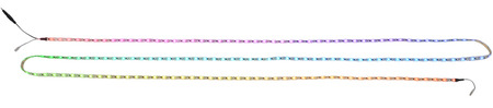
Addressable RGB 60-LED Strip, 5V, 2m (High-Speed TM1804)
Addressable RGB 60-LED Strip, 5V, 2m (High-Speed TM1804)
This 2-meter long strip contains 60 RGB LEDs that can be individually addressed using a one-wire interface, allowing you full control over the color of each RGB LED. The waterproof, adhesive-backed strip runs on 5 V and can be chained with additional high-speed TM1804 strips to form longer runs or cut apart between each LED for shorter segments.
Clearance: These high-speed TM1804-based LED strips are on clearance and will be discontinued when the remaining stock is gone. They are being replaced by similar, newer WS2812B-based strips. The new strips use almost the same control interface, so you can use the same code to control either of them and you can chain one type to the other. However, the two types of strips have different, incompatible connectors, and the order of the red and green channels in the protocol is swapped: the TM1804 colors are sent in red-green-blue order while the WS2812B colors are sent in green-red-blue order.
These RGB LED strips are an easy way to add complex lighting effects to a project. A dedicated driver IC for each LED allows you to control the color and brightness of each LED independently. The strips are available in lengths of 1 meter (30 LEDs), 2 meters (60 LEDs), and 5 meters (150 LEDs).
 |
 |
 |
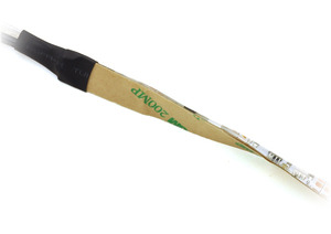 |
| Weatherproof coating and 3M adhesive backing on an addressable RGB LED strip. |
|---|
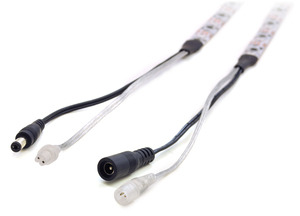 |
| Connectors on an addressable RGB LED strip. |
|---|
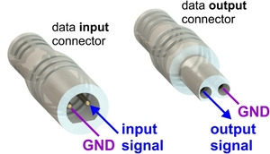 |
| Data connector pinout for the addressable LED strips (products #2543 , #2544, and #2545 only). |
|---|
Each LED strip has four connectors (except for the 5 m strip, which does not have a power output). These can be seen in the adjacent picture, from right to left: data input and power input on one end of the strip, data output and power output on the other end. The data and power output connectors are only used when chaining multiple strips together.
The ground wires on all four connectors are electrically connected.
Note: The white stripe visible on one of the data connector wires is not a good indicator of polarity. Please use the labeled connector diagram to help determine which pin is the signal pin and which is ground. You can also verify the ground pin with a multimeter by checking for continuity between the pin and the outer ring of the power connector.
Multiple LED strips can be chained together by connecting the input connectors from one strip to the output connectors from another strip. When the data connectors on several strips are chained this way, they can be controlled as one continuous strip.
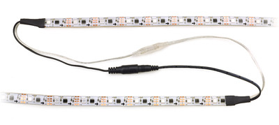 |
| Two addressable RGB LED strips connected. |
|---|
With the 1 m and 2 m LED strips, it is possible to use a single power supply to power several strips by chaining their power connectors together (as long as the power supply can handle the combined current draw of the strips). However, this can result in a significant voltage drop between the beginning and the end of a long chain of strips, which could cause the brightness of the LEDs to vary noticeably down the length of the chain.
Do not chain more than 5 meters of LEDs in a single DC circuit. It is fine to make longer chains with connected data lines, but you should power each five-meter section separately.
The LED strip is divided into segments, with each 33.3 mm segment containing one RGB LED and its driver chip. The strip can be cut apart on the lines between each segment to separate it into two usable shorter sections. To access the connections on either side of the cut, you can peel away the epoxy on the front or the adhesive on the back to expose four copper pads. The data connection is labeled OUT or IN, the positive power connection is labeled +VC, and the two pads in the middle are both connected to ground.
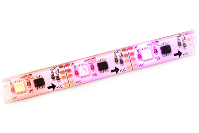 |
| Addressable RGB LED strip segments. |
|---|
These LED strips are controlled by a high-speed one-wire protocol.
The default, idle state of the signal line is low. To update the LED colors, you need to transmit a series of high pulses on the signal line. Each high pulse encodes one bit: a short pulse (0.4 µs) represents a zero, while a long pulse (0.85 µs) represents a one. The time between consecutive rising edges should be 1.25–9.0 µs. After the bits are sent, the signal line should be held low for 24 µs to send a reset command, which makes the new color data take effect. Our tests indicate that the pulse widths do not have to be precise: there is a threshold around 0.6 microseconds that determines whether the pulse is a 0 or a 1, and a wide range of pulse widths on both sides of the threshold will work.
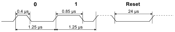 |
| Addressable RGB LED strip data timing diagram (products #2543 , #2544, and #2545 only). |
|---|
The color of each LED is encoded as three LED brightness values, which must be sent in RGB (red-green-blue) order. Each brightness value is encoded as a series of 8 bits, with the most significant bit being transmitted first, so each LED color takes 24 bits. The first color transmitted applies to the LED that is closest to the data input connector, while the second color transmitted applies to the next LED in the strip, and so on.
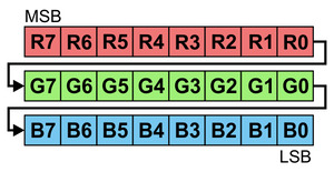 |
| 24 bits represent the color of one LED in an addressable RGB LED strip. |
|---|
To update all the LEDs in the strip, you should send all the colors at once with no pauses. If you send fewer colors than the number of LEDs on the strip, then some LEDs near the end of the strip will not be updated. For example, to update all 30 LEDs on a 1-meter strip, you would send 720 bits encoded as high pulses and then hold the signal line low for 24 µs. If multiple strips are chained together with their data connectors, they can be treated as one longer strip and updated the same way (two chained 1-meter strips behave the same as one 2-meter strip).
Each RGB LED is controlled by a driver IC that receives data on its data input line and passes data on to the next IC using its data output line. The high-speed protocol of the driver allows for fast updates; our library for the Arduino below takes about 1.1 ms to update 30 LEDs, so it is possible to update 15 meters of LED strips faster than 60 Hz. However, constant updates are not necessary; the LED strip can hold its state indefinitely as long as power remains connected.
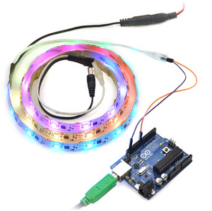 |
| Controlling an addressable RGB LED strip with an Arduino. |
|---|
Since this LED strip does not use a standard protocol, a software bit-banging approach is usually needed to control it from a microcontroller. Because of the sub-microsecond timing, the bit-banging code generally needs to be written in assembly or very carefully optimized C, and interrupts will need to be disabled while sending data to the LED strip. If the interrupts in your code are fast enough, they can be enabled during periods where the signal line is low.
To help you get started quickly, we provide sample code for these microcontroller platforms:
Producent BTC Korporacja sp. z o. o. Lwowska 5 05-120 Legionowo Polska sprzedaz@kamami.pl 22 767 36 20
Osoba odpowiedzialna BTC Korporacja sp. z o. o. Lwowska 5 05-120 Legionowo Polska sprzedaz@kamami.pl 22 767 36 20
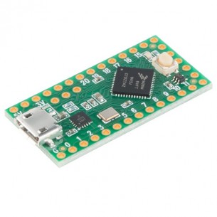
Teensy LC to płytka rozwojowa z mikrokontrolerem Freescale MKL26Z64VFT4 (32-bitowy, rdzeń ARM Cortex-M0+, 48 MHz), wyposażona jest w interfejsy: 3xUART, I2C, I2C, SPI. Płytka może być programowana w Arduino IDE. PJRC TEENSYLC
Brak towaru
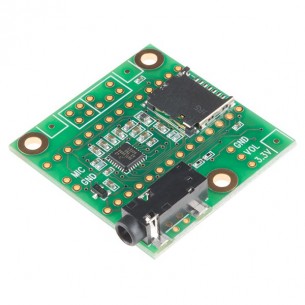
Teensy Audio to rozszerzenie audio (16 bitów, 44,1 kHz) dla płytek Teensy 3.x oparte na kodeku SGTL5000. Umożliwia odtwarzanie i rejestrację dźwięku, syntezowanie dźwięku, dodawanie efektów oraz miksowanie dźwięku. PJRC TEENSY3-AUDIO
Brak towaru
Brak towaru
Brak towaru
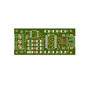
Płytka drukowana do konwertera USB - 1-Wire. AVT1787 A
Brak towaru
Zestaw AVT do samodzielnego montażu konwertera USB - 1-Wire. AVT1787 B
Brak towaru
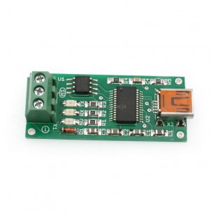
Zmontowany konwerter USB - 1-Wire. AVT1787 C
Brak towaru
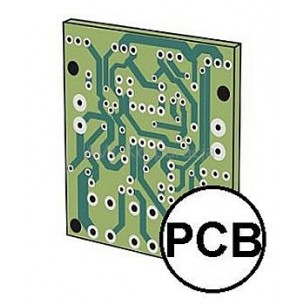
Płytka drukowana do MKP - modułu kontrolno pomiarowego z interfejsem USB. AVT5425 A
Brak towaru
Zestaw AVT do samodzielnego montażu MKP - modułu kontrolno pomiarowego z interfejsem USB. AVT5425 B
Brak towaru
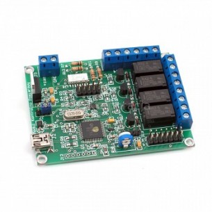
Zmontowany zestaw MKP - moduł kontrolno pomiarowy z interfejsem USB. AVT5425 C
Brak towaru
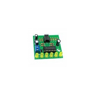
Płytka drukowana do do montażu biegnącego światełka. AVT795 A
Brak towaru
Zestaw AVT do samodzielnego montażu biegnące światełka. AVT795 B
Brak towaru
Zmontowany układ świetlny, biegnące światełko. AVT795 C
Brak towaru
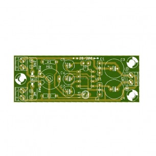
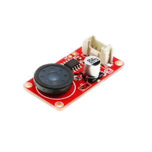
Płytka drukowana do wzmacniacza akustycznego z układem LM386. AVT794 A
Brak towaru
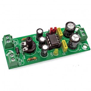
Zestaw AVT do samodzielnego montażu wzmacniacza akustycznego z układem LM386. AVT794 B
Brak towaru
Zmontowany wzmacniacz akustyczny z układem LM386. AVT794 C
Brak towaru
Addressable RGB 60-LED Strip, 5V, 2m (High-Speed TM1804)