


29,13 € Netto
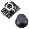
MC33926 Motor Driver Carrier

darmowa wysyłka na terenie Polski dla wszystkich zamówień powyżej 500 PLN

Jeśli Twoja wpłata zostanie zaksięgowana na naszym koncie do godz. 11:00

Każdy konsument może zwrócić zakupiony towar w ciągu 14 dni bez zbędnych pytań
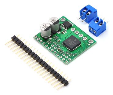
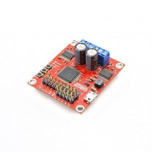
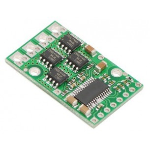
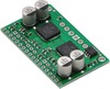
MC33926 Motor Driver Carrier
This breakout board for Freescale’s MC33926 full H-bridge has an operating range of 5 – 28 V and can deliver almost 3 A continuously (5 A peak) to a DC motor. The MC33926 works with 3 – 5 V logic levels, supports ultrasonic (up to 20 kHz) PWM, and features current feedback, under-voltage protection, over-current protection, and over-temperature protection.
 |
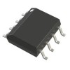
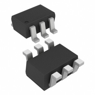
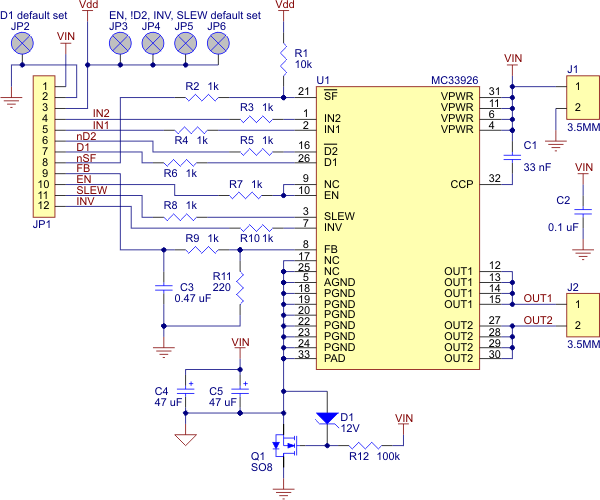
The MC33926 motor driver carrier can supply up to almost 3 A continuous current to a single brushed DC motor at 5 – 28 V, and it can tolerate peak currents up to 5 A for a few seconds, making this a great general-purpose motor driver for medium-sized DC motors. The MC33926 supports ultrasonic (up to 20 kHz) pulse width modulation (PWM) of the motor output voltage, which eliminates the audible switching sounds caused by PWM speed control, and a current feedback circuit outputs an analog voltage on the FB pin that is proportional to the output current. Since this board is a carrier for the Freescale Semiconductor MC33926 H-bridge, we recommend careful reading of the MC33926 datasheet (1MB pdf).
If you have two motors to control, please consider the Dual MC33926 motor driver carrier.
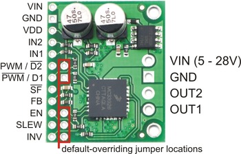 |
The default states of many of the MC33926 logic input pins requires that many external connections be made to use this motor driver. To reduce the number of necessary external connections, the board has five default-overriding jumpers. All of the default-overriding jumpers are tied to VDD, except the D1 jumper, which is tied to GND. All VDD jumper pads are circles; the ground jumper pad is square.
| PIN | Default State | Description |
|---|---|---|
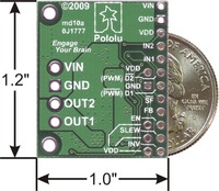
| VIN | HIGH | This is the main 5 – 28 V motor power supply connection, which should typically be made to the larger VIN pad. Operation from 5 – 8 V reduces maximum current output; the device is also protected for transients up to 40 V. The smaller VIN pad can be used to distribute the VIN node to the rest of the application circuit; for lower-current applications, the pin can also be used to power the motor driver and motor. |
| GND | LOW | Ground connection for logic and motor power supplies. |
| OUT2 | HIGH | The motor output pin controlled by IN2. |
| OUT1 | HIGH | The motor output pin controlled by IN1. |
| VDD | HIGH | 3-5 V logic supply connection. This pin is used only for the SF pull-up and default-overriding jumpers; in the rare case where none of those features is used, VDD can be left disconnected. |
| IN2 | HIGH | The logic input control of OUT2. PWM can be applied to this pin (typically done with both disable lines inactive). |
| IN1 | HIGH | The logic input control of OUT1. PWM can be applied to this pin (typically done with both disable lines inactive). |
| PWM / D2 | LOW | Inverted disable input: when D2 is low, OUT1 and OUT2 are set to high impedance. A D2 PWM duty cycle of 70% gives a motor duty cycle of 70%. Typically, only one of the two disable pins is used, but the default is for both disable pins to be active. |
| PWM / D1 | HIGH | Disable input: when D1 is high, OUT1 and OUT2 are set to high impedance. A D1 PWM duty cycle of 70% gives a motor duty cycle of 30%. Typically, only one of the two disable pins is used, but the default is for both disable pins to be active. |
| SF | HIGH | Status flag output: an over-current (short circuit) or over-temperature event will cause SF to be latched LOW. If either of the disable pins (D1 or D2) are disabling the outputs, SF will also be LOW. Otherwise, this pin is weakly pulled high. This allows the SF pins of multiple units to connected to a single input. |
| FB | LOW | The FB output provides analog current-sense feedback of approximately 525 mV per amp. |
| EN | LOW | Enable input: when EN is LOW, the chip is in a low-current sleep mode. |
| SLEW | LOW | Output slew rate selection input. A logical LOW results in a slow output rise time (1.5 ěs – 6 ěs). A logical HIGH selects a fast output rise time (0.2 ěs – 1.45 ěs). This pin should be set HIGH for high-frequency (over 10 kHz) PWM. |
| INV | LOW | A logical high value inverts the meaning of IN1 and IN2. This allows INV to function as a direction line if IN1 and IN2 are set to different values. |
In a typical application, five I/O lines are used to connect the motor driver to a microcontroller: the two input lines, IN1 and IN2, for direction control, one of the disable lines, D1 or D2, for PWM speed control, the status flag, SF, for monitoring motor driver errors, and the current sense output, FB, for monitoring motor current draw (connected to an analog-to-digital converter input). The control lines can be reduced to two pins if PWM signals are applied directly to the two input pins with both disable pins held inactive. A two-pin interface can also be achieved using one of the disable lines for PWM speed control and the INV input for direction control with IN1 and IN2 held at different values (i.e. one set HIGH and the other set LOW). In each of these cases, the other unused lines must be set to enable proper operation. For example, if D2 is used for the PWM input (as is typically the case), D1 must be held low to prevent it from disabling the motor driver. The circuit board provides convenient jumper points for overriding the motor driver defaults without having to connect extra wires to the module.
The current sense and status flag connections are optional, though monitoring of the status flag can allow detection of latched fault conditions. The status flag is an open-drain output, so multiple units can have their status flag pins wired together for applications where I/O pins are scarce and determining which motor driver is experiencing a fault condition is not necessary.
Note that the default state of the enable pin, EN, is LOW, which holds the chip in a low-current sleep mode. You will need to hold this pin high (either with an external connection or via the default-overriding jumper next to the pin) to allow the chip to run.
The MC33926 has under-voltage, over-current, and over-temperature protection. Some protection events are indicated by the status flag pin (SF), which is an active-low pin allowing the SF pin from multiple boards to connected to a single input. If the chip detects an over-current or over-termperature event, the SF is latched LOW and OUT1 and OUT2 are set to high-impedance. To unlatch the status flag pin toggle the D1, D2 , EN or VIN lines. The carrier board has a reverse-protection MOSFET for added protection to the motor driver chip.
The MC33926 motor driver used on the carrier board has a maximum current rating of 5 A continuous. However, the chip by itself will overheat at lower currents. For example, in our tests at room temperature with no forced air flow, the chip was able to deliver 5 A for 5 s and 4 A for 18 s before the chip’s thermal protection started reducing the current. A continuous current of 3 A was right at the over-temperature threshold; in some tests the thermal protection kicked in after a minute, and in other tests the chip delivered 3 A for over five minutes without triggering thermal protection. The actual current you can deliver will depend on how well you can keep the motor driver cool. The carrier’s printed circuit board is designed to draw heat out of the motor driver chip, but performance can be improved by adding a heat sink. Our tests were conducted at 100% duty cycle; PWMing the motor will introduce additional heating proportional to the frequency.
This product can get hot enough to burn you long before the chip overheats. Take care when handling this product and other components connected to it.
Unlike other H-Bridges, the 33926 has a feature that allows it to gracefully reduce current as the current exceeds 5 A or as the chip temperature approaches its limit. This means that if you push the chip close to its limit, you will see less power to the motor, but it might allow you to avoid a complete shutdown.
|
|
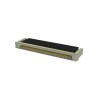
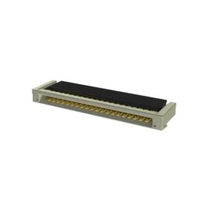
A 20-pin straight breakaway male header is included with the MC33926 carrier board, which can be used to connect the PCB to perfboards or breadboards. The board also includes two 2-pin 3.5mm terminal blocks for making simple motor connections.
 |
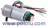 |
75:1 Metal Gearmotor 25Dx54L mm with 48 CPR Encoder |
 |
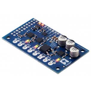
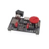
Dual MC33926 Motor Driver Carrier |
 |
TB6612FNG Dual Motor Driver Carrier |
Cechy
Osoba odpowiedzialna BTC Korporacja sp. z o. o. Lwowska 5 05-120 Legionowo Polska sprzedaz@kamami.pl 22 767 36 20
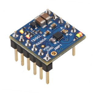
Dwukanałowy sterownik silników DC z interfejsem UART TTL. Jest zasilany napięciem od 4,5 V do 48 V i może dostarczyć prąd o natężeniu do 1,8 A na silnik. Płytka ze złączami do montażu. Pololu 5067
Brak towaru
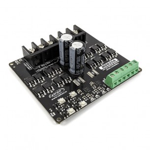
Dwukanałowy sterownik silników prądu stałego (DC) o napięciu pracy od 7 do 30 V i maksymalnym prądzie ciągłym do 10 A. Może być sterowany sygnałem PWM lub za pomocą przycisków. Cytron MDDRC10
Pololu High-Power Motor Driver 36v15
RoboClaw 2x7A Motor Controller (V5B) to dwukanałowy sterownik silników prądu stałego (DC), napięcie pracy: 6-34 V, maksymalny prąd ciągły: 7,5 A, możliwość łatwej realizacji pętli sprzężenia zwrotnego z regulatorem PID, systemy bezpieczeństwa. Pololu 3284
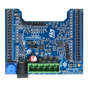
X-NUCLEO-IHM16M1 to płytka rozszerzeń ze sterownikiem trójfazowego bezszczotkowego silnika zasilanym napięciem w zakresie 7-45 V o maksymalnym prądzie wyjściowym 1,5 A w każdym z kanałów. Kompatybilny z STM32 Nucleo. X-NUCLEO-IHM16M1
Dwukanałowy sterownik silników DC z interfejsem I2C. Jest zasilany napięciem od 4,5 V do 48 V i może dostarczyć prąd o natężeniu do 1,8 A na silnik. Płytka ze złączami do montażu. Pololu 5065
Brak towaru
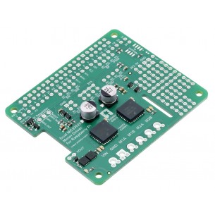
Rozszerzenie dla Raspberry Pi z dwoma sterownikami silników obsługującymi zakres napięć 5-28 V i prąd ciągły 3 A (chwilowy 5 A) każdy. Pololu 2755
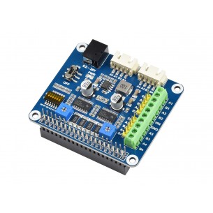
Moduł rozszerzeń ze sterownikiem dwóch silników krokowych oparty na układzie DRV8825. Dedykowany dla minikomputerów Raspberry Pi. Waveshare Stepper Motor HAT
Brak towaru
Pololu High-Power Motor Driver 36v9
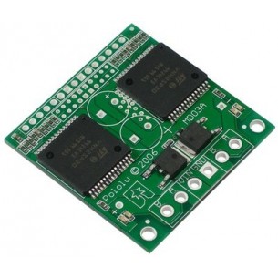
Dual VNH2SP30 Motor Driver Carrier MD03A
Sterownik silników DC, który pozwala na kontrolowanie ruchu trzech napędów za pomocą interfejsu I2C. Pololu 5035
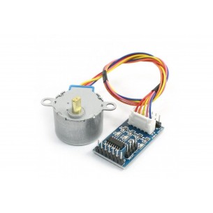
Zestaw składający się z modułu sterownika silnika krokowego opartego na układzie ULN2003 oraz silnika krokowego zasilanego napięciem 5V.
Brak towaru
Jednokanałowy sterownik silników DC z interfejsem I2C. Jest zasilany napięciem od 1,8 V do 22 V i może dostarczyć prąd o natężeniu do 1,8 A. Płytka z przylutowanymi złączami. Pololu 5074
Dwukanałowy sterownik silników prądu stałego (DC) o napięciu pracy od 6 do 30 V i maksymalnym prądzie ciągłym do 20 A. Może być sterowany sygnałem PWM lub za pomocą wbudowanych przycisków. Cytron MDD20A
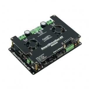
Dwukanałowy sterownik silników DC o napięciu pracy od 7 do 45 V i prądzie ciągłym do 60 A na kanał. Może być sterowany sygnałem analogowym, PWM, UART, RC lub za pomocą wbudowanych przycisków. Cytron MDDS60
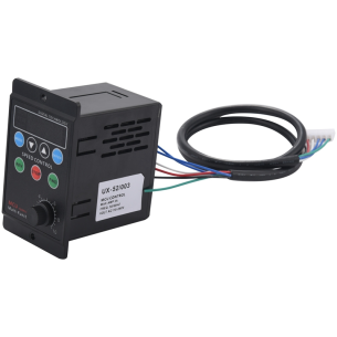
Panelowy kontroler prędkości silnika szczotkowego UX-52 to wszechstronne urządzenie z regulacją prędkości od 90 do 1400 obr./min. Oferuje precyzyjną kontrolę nad silnikami o napięciu wejściowym 220VAC, charakteryzując się solidną konstrukcją i wygodnym wyświetlaczem cyfrowym.
MC33926 Motor Driver Carrier