


36,56 zł Netto
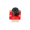
Sterownik silników A4990 stanowi solidne i bezpieczne rozwiązanie do sterowania dwoma silnikami DC przy napięciach do 32 V. Dzięki wbudowanemu ograniczeniu prądu, licznym zabezpieczeniom oraz kompaktowej formie moduł sprawdzi się w projektach wymagających niezawodnej pracy, ochrony elektroniki oraz prostego sterowania z mikrokontrolera. Pololu 2137
Sterownik A4990 to kompaktowy moduł sterownika silników oparty na układzie A4990 firmy Allegro MicroSystems, przeznaczony do dwukierunkowego sterowania dwoma szczotkowymi silnikami DC lub jednym silnikiem krokowym bipolarnym. Moduł obsługuje szeroki zakres napięć zasilania od 6 do 32 V, dzięki czemu znajduje zastosowanie w projektach robotycznych, automatyce oraz układach mobilnych zasilanych z wyższych napięć.
Płytka zawiera komplet elementów SMD, w tym rezystory pomiarowe prądu oraz dodatkowy tranzystor MOSFET zapewniający ochronę przed odwrotną polaryzacją zasilania.
Cechy
Producent BTC Korporacja sp. z o. o. Lwowska 5 05-120 Legionowo Polska sprzedaz@kamami.pl 22 767 36 20
Osoba odpowiedzialna BTC Korporacja sp. z o. o. Lwowska 5 05-120 Legionowo Polska sprzedaz@kamami.pl 22 767 36 20
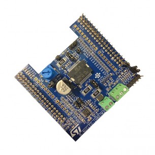
Shield do STM32 Nucleo pozwalający na dodanie możliwości obsługi trójfazowego silnika bezszczotkowego (BLDC) lub synchronicznego z magnesami trwałymi (PMSM). Do sterowania wykorzystuje układ L6230. X-NUCLEO-IHM07M1
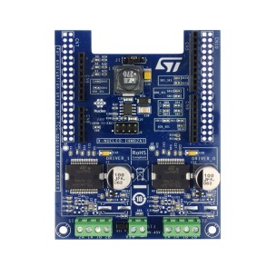
X-NUCLEO-IHM02A1 to moduł sterownika dwóch silników krokowych oparty na dwóch układach L6470. Poziom logiczny 3,3 lub 5 V, sterowanie przez SPI. Złącza zgodne z Arduino i STM32 Nucleo
Brak towaru
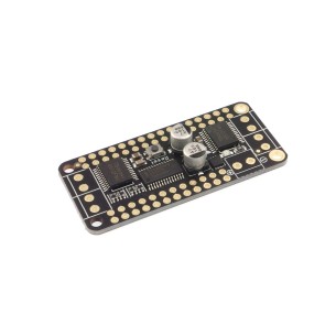
Nakładka przeznaczona do użycia z płytkimi z serii Feather zawiera dwa układy TB6612 pozwalające na sterowanie silnikami prądu stałego lub silnikami krokowymi. Do komunikacji z nakładką wykorzystywany jest interfejs I2C. Adafruit 2927
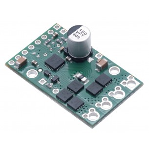
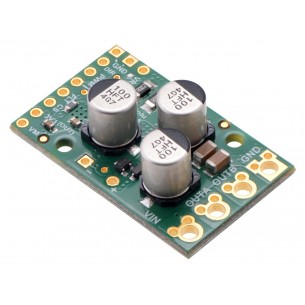
Pololu G2 24v13 High Power to miniaturowy sterownik silnika DC. Zasilanie sterownika: 6,5 - 40 V. Wydajność prądowa modułu: 13 A. Moduł posiada zabezpieczenie przed napięciem wstecznym i przepięciami. Pololu 2992
Brak towaru
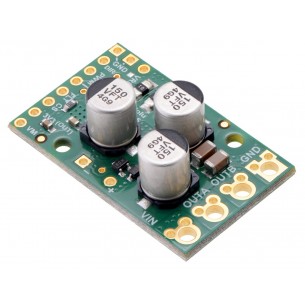
Pololu G2 18v17 to miniaturowy sterownik silnika DC. Zasilanie sterownika: 6,5 - 30 V. Wydajność prądowa modułu: 17 A.
Moduł posiada zabezpieczenie przed napięciem wstecznym i przepięciami. Pololu 2991
Brak towaru
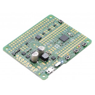
Moduł pozwala połączyć zalety Raspberry Pi i Arduino, wyposażony jest w mikrokontroler ATmega32u4 z botloaderem zgodnym z Arduino i podwójny sterownik silników. Pololu 3119
Moduł pozwala połączyć zalety Raspberry Pi i Arduino, wyposażony jest w mikrokontroler ATmega32u4 z botloaderem zgodnym z Arduino i podwójny sterownik silników. Pololu 3118
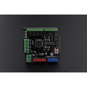
Moduł rozszerzeń (shield) ze sterownikiem silnika krokowego dla Arduino. Pozwala na sterowanie napędami pracującymi z napięciem do 40 V i poborem prądu do 2 A na cewkę. DFRobot DRI0035
Brak towaru
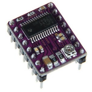
DRV8825 Stepper Motor Driver Carrier to sterownik silnika krokowego z układem DRV8825, pozwala na zasilanie silnika bipolarnego prądem do 1,5A na fazę, bez użycia radiatora. Układ może być zasilany napięciem do 45V, w zestawie znajduje się radiator. Jest kompatybilny z Pololu 2133
Brak towaru
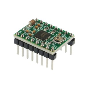
Sterownik silnika krokowego z układem Allegro A4988 (A4988 Stepper Motor Driver Carrier) pozwala na zasilanie silnika bipolarnego prądem do 2A na fazę. Układ może być zasilany napięciem do 35V, w zestawie znajduje się radiator. Jest kompatybilny z Pololu 1182
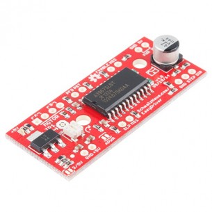
Sterownik silnika krokowego, napięcie zasilania cewek silnika 6..30 V, napięcie pracy logiki sterownika 0..5 V lub 0..3,3 V. Możliwa regulacja prądu sterowania na fazę obrotu podczas pracy sterownika. ROB-12779
Brak towaru
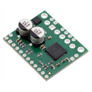
Pololu G2 18v25 to miniaturowy sterownik silnika DC. Zasilanie sterownika: 6.5V...30V. Wydajność prądowa modułu: 25A.
Moduł posiada zabezpieczenie przed napięciem wstecznym i przepięciami. Pololu 2994
Brak towaru
Pololu G2 24v21 to miniaturowy sterownik silnika DC. Zasilanie sterownika: 6.5V...40V. Wydajność prądowa modułu: 21A.
Moduł posiada zabezpieczenie przed napięciem wstecznym i przepięciami. Pololu 2995
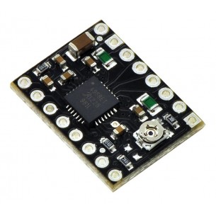
Sterownik silnika krokowego A4988 operujący na napięciach 8..35 V i prądzie 1,2 A. Pololu 2128
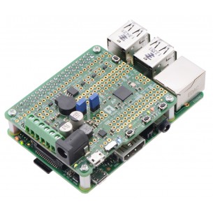
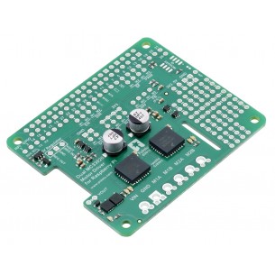
Rozszerzenie dla Raspberry Pi z dwoma sterownikami silników obsługującymi zakres napięć 5-28 V i prąd ciągły 3 A (chwilowy 5 A) każdy. Pololu 2755
Brak towaru
Sterownik silnika krokowego AMIS-30543 operujący w zakresie napięć 6..30 V i prądzie 1,8 A. Pololu 2970
Sterownik silników A4990 stanowi solidne i bezpieczne rozwiązanie do sterowania dwoma silnikami DC przy napięciach do 32 V. Dzięki wbudowanemu ograniczeniu prądu, licznym zabezpieczeniom oraz kompaktowej formie moduł sprawdzi się w projektach wymagających niezawodnej pracy, ochrony elektroniki oraz prostego sterowania z mikrokontrolera. Pololu 2137