


zł36.56 tax excl.
A4990 Dual Motor Driver Carrier
A4990 Dual Motor Driver Carrier
This compact breakout board makes it easy to use Allegro’s A4990 dual motor driver, which can control two bidirectional DC motors over a wide operating voltage range of 6 to 32 V. It is capable of delivering a continuous 0.7 A to each motor channel, and onboard sense resistors enable the A4990 to limit the peak motor current to about 0.9 A per channel. The driver also features protection against reverse-voltage, under-voltage, over-voltage, over-current, and over-temperature.
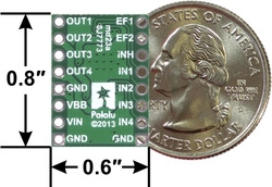 |
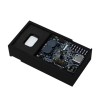
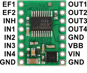
| A4990 dual motor driver carrier, bottom view with dimensions. |
|---|
Allegro’s A4990 is a dual H-bridge motor driver IC that can be used for bidirectional control of two brushed DC motors at 6 to 32 V. It can supply up to 0.7 A continuously to each motor channel, and the current control feature of the A4990 limits the peak motor current to about 0.9 A per channel with the onboard sense resistors, making this a good choice for small, low-current motors that run on relatively high voltages. Since this board is a carrier for the A4990, we recommend careful reading of the A4990 datasheet (301k pdf). The board ships populated with all of its SMD components, including the A4990 and an additional FET for reverse battery protection.
For a single-channel driver with a DIR/PWM interface and a similar operating voltage range, please consider our DRV8801 carrier. For lower-voltage alternatives to the A4990, consider our DRV8833 and DRV8835 dual motor driver carriers.
1 The overvoltage protection typically kicks in at 34 V, but it can trigger at voltages as low as 32 V.
2 While the A4990 can tolerate input voltages as high as 50 V, the reverse-voltage protection MOSFET is only rated for 40 V.
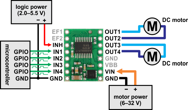 |
| Minimal wiring diagram for connecting a microcontroller to an A4990 dual motor driver carrier. |
|---|
In a typical application, power connections are made on one side of the board and control connections are made on the other. The INH (inhibit) pin is pulled low internally, disabling the A4990 by default, and must be driven high (2.0–5.5 V) in order to enable the driver.
The OUT1 and OUT2 pins form one motor channel while the OUT3 and OUT4 pins form the other. The state of each output is controlled by a corresponding input (IN1 through IN4); note that IN2 and IN4 are inverted inputs. All four INx pins are pulled to their inactive states by default. See the truth tables in the A4990 datasheet for more information on how the inputs affect the driver outputs.
The EF1 and EF2 pins are open-drain outputs that are driven low by the chip to indicate active faults (the datasheet describes what each combination of EF1 and EF2 means). Otherwise, these pins remain in a floating state, so you will need to connect external pull-up resistors (or use microcontroller inputs with their built-in pull-ups enabled) if you want to monitor fault conditions on the driver.
 |
| PIN | Default State | Description |
|---|---|---|
| VIN | 6–32 V motor power supply connection. | |
| VBB | This pin gives access to the motor power supply after the reverse-voltage protection MOSFET (see the board schematic below). It can be used to supply reverse-protected power to other components in the system. It is generally intended as an output, but it can also be used to supply board power. | |
| GND | Ground connection points for the motor and logic power supplies. The control source and the motor driver must share a common ground. | |
| OUT1 | Motor A output +. | |
| OUT2 | Motor A output â?’. | |
| OUT3 | Motor B output +. | |
| OUT4 | Motor B output â?’. | |
| IN1 | LOW | Control input for OUT1. PWM can be applied to this pin. |
| IN2 | HIGH | Inverted control input for OUT2. PWM can be applied to this pin. |
| IN3 | LOW | Control input for OUT3. PWM can be applied to this pin. |
| IN4 | HIGH | Inverted control input for OUT4. PWM can be applied to this pin. |
| INH | LOW | Logic input that puts the A4990 into a low-power sleep mode when low. |
| EF1 | floating | Error flag output 1: driven low to indicate active fault status; floating otherwise. |
| EF2 | floating | Error flag output 2: driven low to indicate active fault status; floating otherwise. |
The A4990 can actively limit the current through the motors by using a fixed-frequency PWM current regulation (current chopping). This carrier board connects 0.075 Ω resistors to the current sense pins, which sets the current limit to a nominal 1 A per channel. In our tests, the board actually limited the motor current to slightly above 0.9 A.
Even though the driver limits the motor current to about 0.9 A per channel, the chip by itself will overheat at lower currents. For example, in our tests at room temperature with no forced air flow, the chip was able to deliver 0.9 A per channel for approximately 20 s before the chip’s thermal protection kicked in. A continuous current of 0.7 A per channel was sustainable for many minutes without triggering a thermal shutdown. The actual current you can deliver will depend on how well you can keep the motor driver cool. The carrier’s printed circuit board is designed to draw heat out of the motor driver chip, but performance can be improved by adding a heat sink. Our tests were conducted at 100% duty cycle; PWMing the inputs will introduce additional heating proportional to the frequency (unless the A4990 is already PWMing the outputs to limit the current).
This product can get hot enough to burn you long before the chip overheats. Take care when handling this product and other components connected to it.
|
|
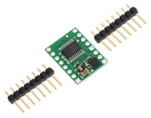
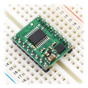
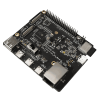
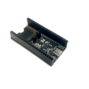
Two 1A—8-pin breakaway 0.1" male headers are included with the A4990 motor driver carrier, which can be soldered in to use the driver with perfboards, breadboards, or 0.1" female connectors. (The headers might ship as a single 1A—16 piece that can be broken in half.) When used with these header pins, the board can be oriented with the parts visible, as shown in the right picture above, or with the silkscreen visible, by soldering the headers in from the opposite side. You can also solder your motor leads and other connections directly to the board.
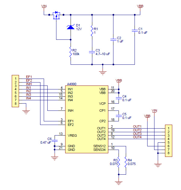 |
| A4990 Dual Motor Driver Carrier schematic diagram. |
|---|
This schematic is also available as a downloadable pdf (166k pdf).
Data sheet
Manufacturer BTC Korporacja sp. z o. o. Lwowska 5 05-120 Legionowo Poland sprzedaz@kamami.pl 22 767 36 20
Responsible person BTC Korporacja sp. z o. o. Lwowska 5 05-120 Legionowo Poland sprzedaz@kamami.pl 22 767 36 20
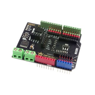
Gravity: IO Expansion & Motor Driver Shield is an Arduino compatible expansion board that provides digital I / O ports, analog I2C, SPI and UART interfaces, as well as a DC motor driver. DFRobot DFR0502
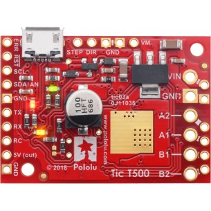
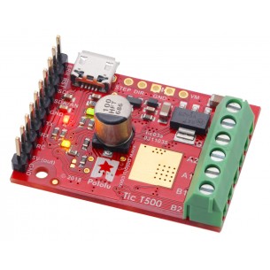
Tic T500 USB Multi-Interface Stepper Motor Controller
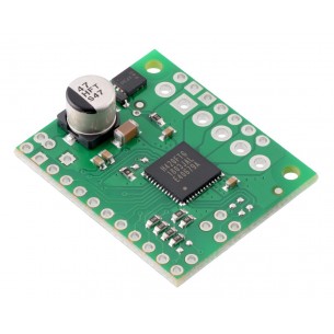
Tic T500 USB is a stepper motor driver based on the MP6500 chip. It allows you to control the stepper motor whose voltage on the coil is 4.5-35V, the maximum current per coil is up to 1.5A. The controller can be controlled by: USB, TTL, I2C, RC (PWM model) etc. Pololu 3134
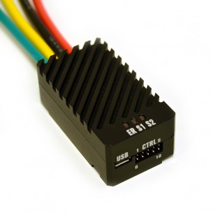
The RoboClaw Solo motor controllers from Basicmicro (formerly Ion Motion Control) can control a single brushed DC motor using USB serial, TTL serial, RC, or analog inputs. An integrated quadrature decoder make it easy to create a closed-loop speed control system.
No product available!
The RoboClaw Solo motor controllers from Basicmicro (formerly Ion Motion Control) can control a single brushed DC motor using USB serial, TTL serial, RC, or analog inputs. Pololu 3291
No product available!
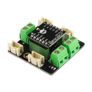
2x1.2A DC Motor Driver is a dual controller of DC motors with a Gravity connector, supplied with 2.5 ... 12V voltage with a maximum current consumption of 1.2A (3.2A peak) per channel. DFRobot DRI0044-A
2x1.2A DC Motor Driver is a dual controller of DC motors powered with 2.5 ... 12V voltage with a maximum current consumption of 1.2A (3.2A peak) per channel. DFRobot DRI0044
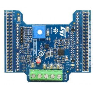
The X-NUCLEO-IHM17M1 is a low voltage three-phase brushless DC motor driver expansion board based on the STSPIN233 for STM32 Nucleo. It provides an affordable and easy-to-use solution for the implementation of portable motor driving applications such as thermal printers, robotics and toys
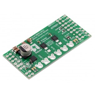
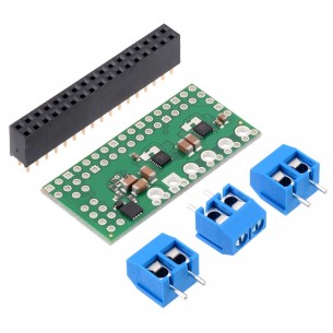
Dual MAX14870 Motor Driver is a dual DC motor controller compatible with the Arduino standard that allows you to control two DC motors with 4.5 ... 36V continuous current of 1.7A. Polol 2519
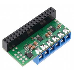
Dual MAX14870 Motor Driver is a dual DC driver compatible with Raspberry Pi that allows you to control two DC motors with 4.5-36V continuous current of 1.7A. Pololu 3759
ual MAX14870 Motor Driver is a dual DC motor driver compatible with the Raspberry Pi standard that allows you to control two DC motors with 4.5 ... 36V continuous current of 1.7A. Pololu 3758
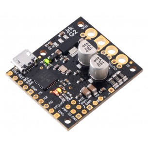
This powerful motor controller makes closed-loop speed or position (but not both!) control of a brushed DC motor easy, with quick configuration over USB using our free software. It supports five control interfaces: USB, TTL serial, I²C, analog voltage (potentiometer), and hobby radio control (RC).
DC motor driver with voltage 6.5 ... 40V and maximum continuous current 13A. It has the ability to easily implement the feedback loop and numerous control interfaces. Polol 3147
DC motor driver with voltage 6.5..30V and maximum continuous current 27A. It has the ability to easily implement the feedback loop and numerous control interfaces. Polol 3148
No product available!
DC motor driver with voltage 6.5..40V and maximum continuous current 21A. It has the ability to easily implement the feedback loop and numerous control interfaces. Polol 3149
No product available!
The controller enables to supply the motors with voltage in the range of 10-47V and power consumption in continuous operation of 1.7A (4.5A peak) for each channel in dual or 3.4A mode (9A peak) in single channel mode. Pololu 2999
A4990 Dual Motor Driver Carrier