


50,77 zł Netto
Moduł pozwala na zmianę prędkości obrotowej silnika poprzez regulację PWM o częstotliowści do 500 kHz. Posiada wbudowane zabezpieczenie przed podaniem odwrotnej polaryzacji zasilania oraz zabezpieczenie termiczne. Pololu 2960

darmowa wysyłka na terenie Polski dla wszystkich zamówień powyżej 500 PLN

Jeśli Twoja wpłata zostanie zaksięgowana na naszym koncie do godz. 11:00

Każdy konsument może zwrócić zakupiony towar w ciągu 14 dni bez zbędnych pytań
Pololu - 2960
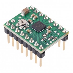
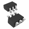
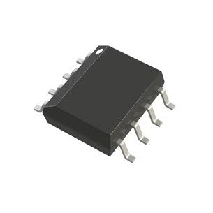
This compact breakout board is for ROHM’s BD65496MUV motor driver, which offers an operating voltage range of 2 V to 16 V and can deliver a continuous 1.2 A (5 A peak for a few milliseconds) to a single brushed DC motor. The motor driver features variable switching speed, allowing for PWM frequencies up to 500 kHz, two drive mode options, and built-in under-voltage and over-temperature protection; our carrier also adds reverse-voltage protection.
DESCRIPTION
Overview
The BD65496MUV from ROHM is a tiny H-bridge motor driver IC that can be used for bidirectional control of one brushed DC motor at 2 V to 16 V. It can supply up to about 1.2 A continuously and can tolerate peak currents up to 5 A for a few milliseconds. The BD65496MUV is a great IC, but its small surface-mount package makes it difficult for the typical student or hobbyist to use; our breakout board makes it easy to use with standard solderless breadboards and 0.1″ perfboards. Since this board is a carrier for the BD65496MUV, we recommend careful reading of the BD65496MUV datasheet (481k pdf). The board ships populated with SMD components, including the BD65496MUV and a reverse battery protection circuit.
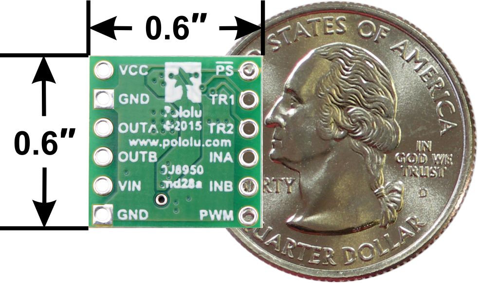
BD65496MUV Single Brushed DC Motor Driver Carrier,
bottom view with dimensions.
Features
Included hardware
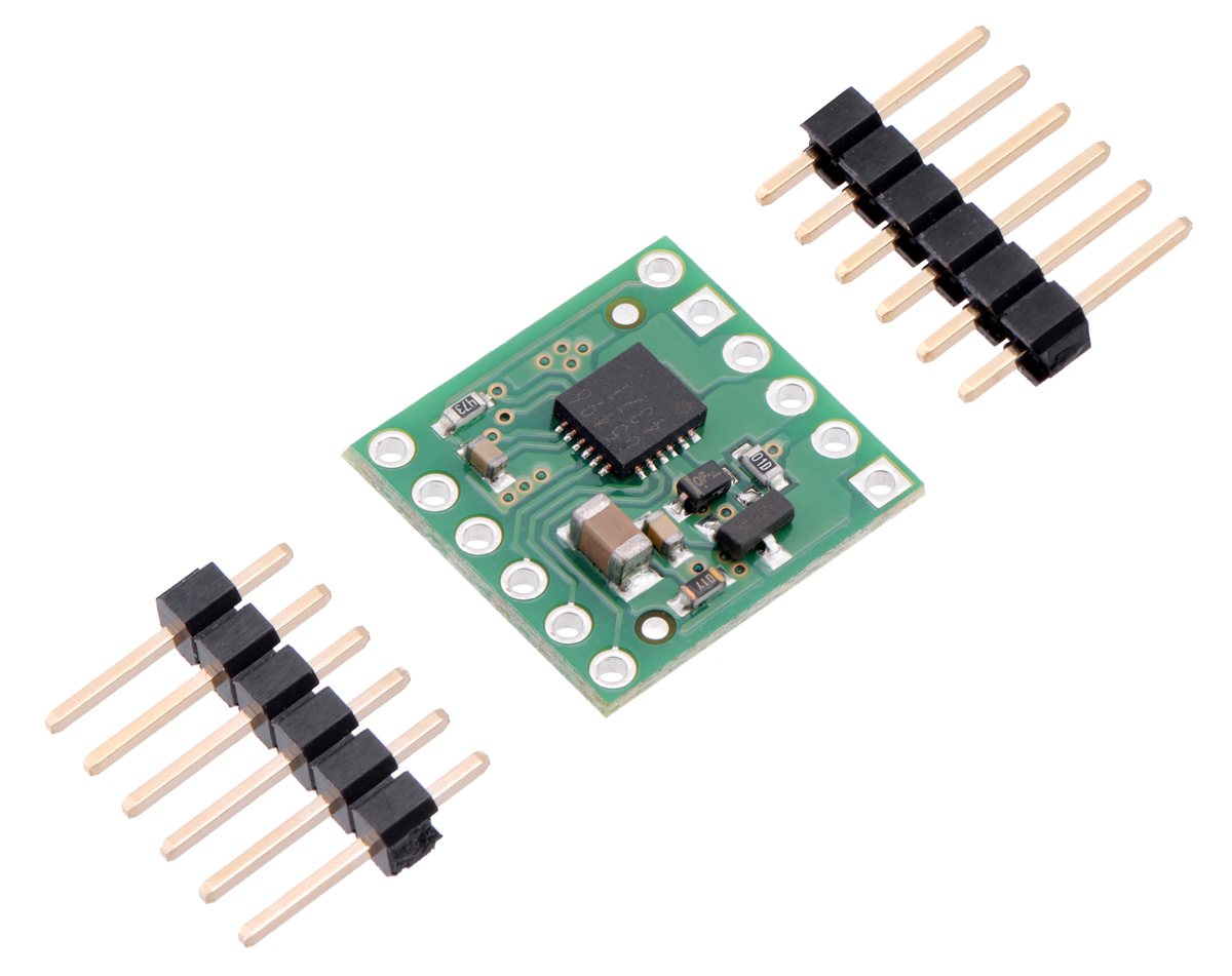
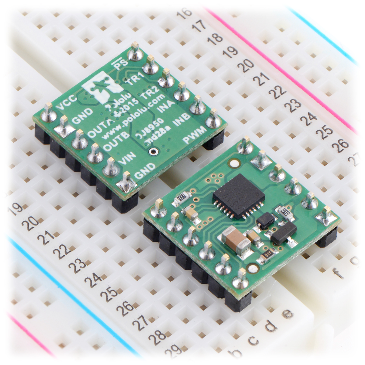
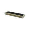
Two 1×6-pin breakaway 0.1″ male headers are included with the BD65496MUV motor driver carrier, which can be soldered in to use the driver with breadboards, perfboards, or 0.1″ female connectors. (The headers might ship as a single 1×12 piece that can be broken in half.) The right picture above shows the two possible board orientations when used with these header pins (parts visible or silkscreen visible). You can also solder your motor leads and other connections directly to the board.
Using the motor driver
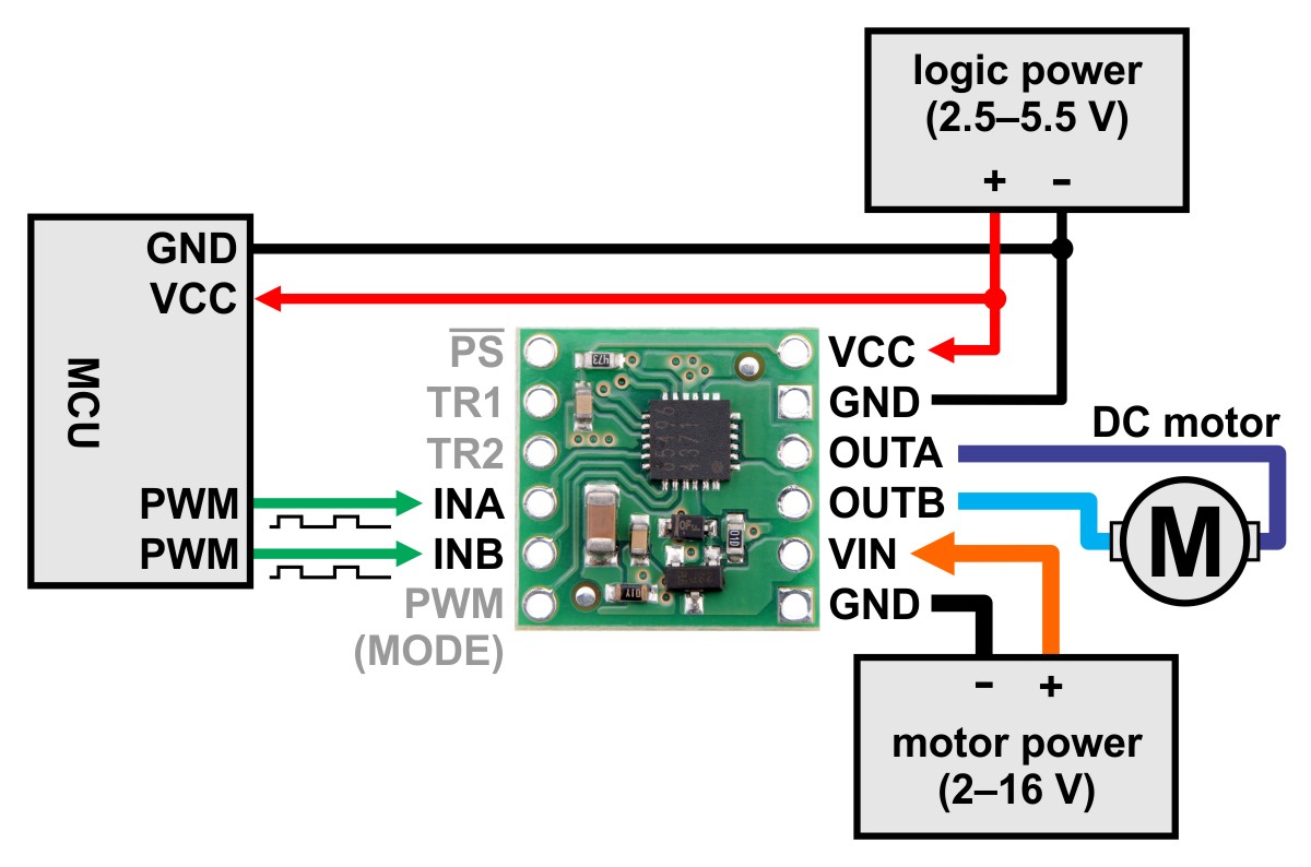
Minimal wiring diagram for connecting a microcontroller
to a BD65496MUV Single Brushed DC Motor Driver Carrier
(default IN/IN mode).
Motor and power connections are made on one side of the board and control connections are made on the other. The driver requires an operating voltage between 2 V and 16 V to be supplied to the reverse-protected power input, VIN, and a logic voltage between 2.5 V and 5.5 V to be supplied to the VCC pin; the logic voltage can typically be supplied by or shared with the controlling device.
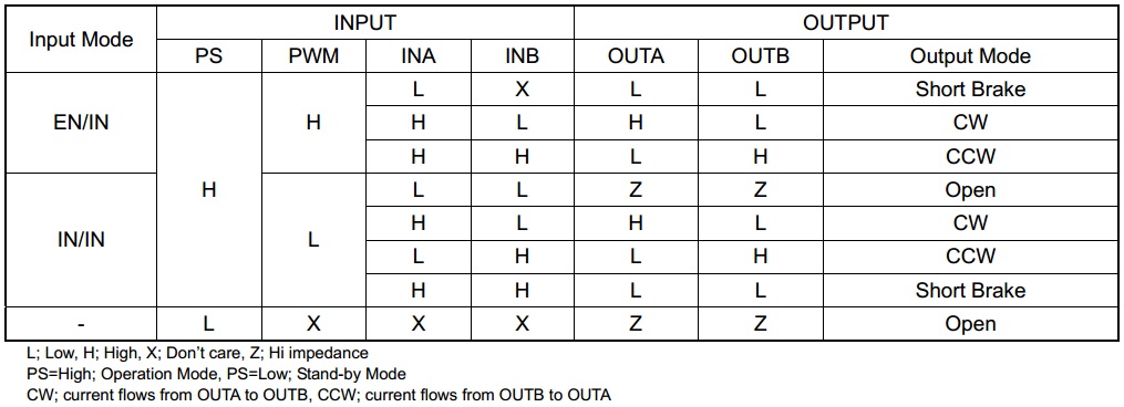
The BD65496MUV offers two possible control interface modes: IN/IN and EN/IN. The PWM (MODE) pin is used to select the control interface. If the PWM (MODE) pin is left disconnected or driven low, as shown in the minimal wiring diagram above, the selected interface is IN/IN, which generally requires two PWM signals, one for INA and another for INB. If this pin is driven high, as shown in the wiring diagram below, the selected interface is EN/IN, which turns the INB pin into a “motor direction” input and the INA pin into an enable input that can be supplied with a PWM signal to control speed.

Minimal wiring diagram for connecting a microcontroller
to a BD65496MUV Single Brushed DC Motor Driver Carrier
(EN/IN mode).
The PS (power save) pin can be driven low to put the driver into a low-power state and turn off the motor outputs, which is useful if you want to let the motor coast. The PS pin is pulled high through a 47 kΩ pull-up resistor on the carrier board so that the driver is enabled by default; the quiescent current draw of the board will be dominated by the current through this resistor when the pin is driven low to put the driver to sleep. In most applications, this pin can be left disconnected or can serve primarily as a way to enable coasting. For applications where a low-power mode is desirable, the 47 kΩ pull-up resistor can be removed (this resistor is located right next to the PS pin), or the logic voltage (VCC) for the driver can be dynamically supplied by a digital output of your microcontroller.
The following truth table (taken directly from the BD65496MUV datasheet) shows how the driver operates:
Pinout
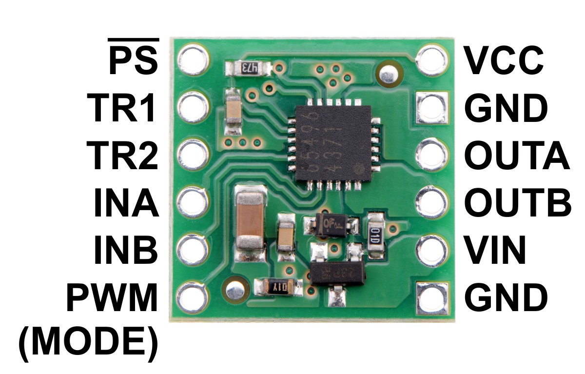
| PIN | Default State | Description |
|---|---|---|
| VIN | Reverse-protected power supply input; supply this pin with 2 V to 16 V. | |
| VCC | 2.5 V to 5.5 V logic power supply connection. Logic supply current draw is typically only a few milliamps at most, so in many applications this pin can optionally be dynamically powered by a microcontroller digital output. | |
| GND | Ground connection points for the motor and logic supplies. The control source and the motor driver must share a common ground. | |
| OUTA | H-bridge output A. | |
| OUTB | H-bridge output B. | |
| PWM (MODE) | LOW | Drive mode selection pin. LOW=IN/IN; HIGH=EN/IN. |
| INA | LOW | Motor control input A (functions like an enable pin in EN/IN mode). |
| INB | LOW | Motor control input B (functions like a direction pin in EN/IN mode). |
| PS | HIGH | Sleep/coast input. Drive low to tri-state the driver outputs and enable power-save mode. |
| TR1 | LOW | Turn-on and turn-off time selection input 1. |
| TR2 | LOW | Turn-on and turn-off time selection input 2. |
All of the driver inputs except PS are internally pulled low through 100 kΩ pull-down resistors. The PS pin is pulled high on the carrier board through a 47 kΩ pull-up resistor that overpowers the driver IC’s internal 300 kΩ pull-down.
The TR1 and TR2 pins control the driver’s turn-on and turn-off time. Both pins are low by default, resulting in a default turn-on time of 150 ns (typical) and a default turn-off time of 50 ns (typical); this allows for PWM frequencies up to 500 kHz. If such a high switching frequency is not required, the TR1 and TR2 inputs can be configured for longer turn-on and turn-off times to help reduce electromagnetic interference (EMI). See the datasheet for more information.
Real-world power dissipation considerations
The BD65496MUV datasheet rates this driver for a maximum continuous current of 1.2 A. In our tests, we found that the chip was able to deliver 1.2 A comfortably over the full operating voltage range, with the driver temperature only approaching the thermal shut down point at the very low end of the motor supply range. At 9 V in, we did not see the driver’s thermal shutdown activate until we pushed the continuous current past 1.5 A for many minutes, but we generally advise against running so close to the limit that the driver overheats. Our tests were conducted at 100% duty cycle with no forced air flow; PWMing the motor will introduce additional heating proportional to the frequency.
SPECIFICATIONS
Dimensions
| Size: | 0.6″ × 0.6″1 |
|---|---|
| Weight: | 0.6 g1 |
General specifications
| Motor driver: | BD65496MUV |
|---|---|
| Motor channels: | 1 |
| Minimum operating voltage: | 2 V |
| Maximum operating voltage: | 16 V |
| Continuous output current per channel: | 1.2 A |
| Peak output current per channel: | 5 A2 |
| Maximum PWM frequency: | 500 kHz3 |
| Minimum logic voltage: | 2.5 V |
| Maximum logic voltage: | 5.5 V |
| Reverse voltage protection?: | YES |
Notes:
1 Without included hardware.
2 For no longer than 10 ms; duty cycle < 5%.
3 TR1 and TR2 low.
RESOURCES
File downloads
Cechy
Osoba odpowiedzialna BTC Korporacja sp. z o. o. Lwowska 5 05-120 Legionowo Polska sprzedaz@kamami.pl 22 767 36 20
Kompaktowy sterownik silnika krokowego z układem TMC2208 o napięciu pracy od 4 do 35 V. Oferuje płynną, cichą pracę, wysoką wydajność, różnorodne tryby pracy oraz łatwą konfigurację. Jest sterowany przez interfejs STEP/DIR i stanowi idealne rozwiązanie dla drukarek 3D oraz podobnych zastosowań
Brak towaru
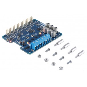
Pololu High-Power Motor Driver 24v12
Płytka rozszerzająca ze sterownikiem silników krokowych L6474. wyposażona została w złącze kompatybilne z Arduino Uno R3 i STM32 Nucleo. STMicroelectronics X-NUCLEO-IHM01A1
Sterownik silników krokowych, który może pracować z napięciem z zakresu od 24 do 110 VDC lub od 18 do 80 VAC oraz maksymalnym prądem do 8,4 A. Umożliwia konfigurację mikro kroku w zakresie od 2 do 256. 2DM860H
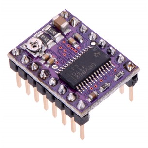
DRV8825 Stepper Motor Driver Carrier to sterownik silnika krokowego z układem DRV8825, pozwala na zasilanie silnika bipolarnego prądem do 1,5A na fazę, bez użycia radiatora. Układ może być zasilany napięciem do 45V, w zestawie znajduje się radiator. Jest kompatybilny z Pololu 2133
Brak towaru
Moduł sterownika silnika krokowego TB67S128FTG zasilanego napięciem 6,5-44V i prądzie pracy 2,1A. Sterownik pozwala na kontrolowanie ruchu silnika aż z 8 różnymi rozdzielczościami (do 1/128 kroku). Pololu 2998
Sterownik silników DC, który pozwala na kontrolowanie ruchu dwóch napędów za pomocą interfejsu I2C. Płytka z przylutowanymi złączami. Pololu 5057
Brak towaru
Sterownik silników DC, który pozwala na kontrolowanie ruchu dwóch napędów za pomocą interfejsu I2C. Płytka ze złączami do montażu. Pololu 5055
Brak towaru
Sterownik silników DC, który pozwala na kontrolowanie ruchu dwóch napędów za pomocą interfejsu I2C. Płytka z przylutowanymi złączami. Pololu 5048
Brak towaru
Jednokanałowy sterownik silnika DC o napięciu pracy od 10 do 45 V i prądzie ciągłym do 40 A. Może być sterowany sygnałem analogowym, PWM, UART, RC lub za pomocą wbudowanych przycisków. Cytron MDS40B
DRV8825 Stepper Motor Driver Carrier to sterownik silnika krokowego z układem DRV8825, pozwala na zasilanie silnika bipolarnego prądem do 1,5 A na fazę, bez użycia radiatora. Układ może być zasilany napięciem do 45 V. Pololu 2982
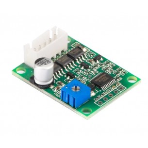
Sterownik bezszczotkowego silnika prądu stałego (BLDC). Może obsługiwać silniki zasilane napięciem od 6 do 20 V o poborze prądu do 3 A
Moduł ze sterownikiem silnika krokowego oparty na układzie DRV8434A. Pozwala na zasilanie silnika bipolarnego prądem do 1,2 A na fazę i napięciem od 4,5 V do 45 V. Komunikacja przez interfejs SPI. Pololu 3767
Brak towaru
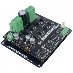
Moduł sterownika dwóch silników szczotkowych DC o wydajności prądowej do 5 A na kanał. Może współpracować z pakietami LiPo 2S i 3S
Dwukanałowy sterownik silników prądu stałego (DC) o napięciu pracy od 6 do 30 V i maksymalnym prądzie ciągłym do 20 A. Może być sterowany sygnałem PWM lub za pomocą wbudowanych przycisków. Cytron MDD20A
Moduł z dwoma sterownikami silników DC DRV8830. Płytka została wyposażona w złącze Grove i komunikuje się przez interfejs I2C. Seeed Studio 105020010
Moduł pozwala na zmianę prędkości obrotowej silnika poprzez regulację PWM o częstotliowści do 500 kHz. Posiada wbudowane zabezpieczenie przed podaniem odwrotnej polaryzacji zasilania oraz zabezpieczenie termiczne. Pololu 2960