


57,79 zł Netto
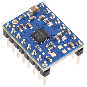
Moduł pozwala na zmianę prędkości obrotowej silnika poprzez regulację PWM o częstotliowści do 500 kHz. Posiada wbudowane zabezpieczenie przed podaniem odwrotnej polaryzacji zasilania oraz zabezpieczenie termiczne. Pololu 2960
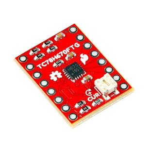
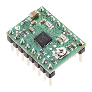
Opis
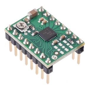
Kompaktowa płytka pośrednia (breakout board) oparta na sterowniku silników ROHM BD65496MUV, przeznaczona do dwukierunkowego sterowania jednym szczotkowym silnikiem DC. Układ pracuje w szerokim zakresie napięć 2 V – 16 V i umożliwia dostarczenie do 1,2 A prądu ciągłego (do 5 A w impulsie przez kilka milisekund).
Dzięki bardzo małym rozmiarom oryginalnego układu SMD, jego samodzielne użycie bywa trudne – wersja Pololu rozwiązuje ten problem, udostępniając wyprowadzenia w rastrze 2,54 mm, idealne do płytek stykowych i prototypowych. Dodatkowo płytka zawiera zabezpieczenie przed odwrotną polaryzacją zasilania.
Silnik, przewody oraz mikrokontroler nie są dołączone
Cechy
Producent BTC Korporacja sp. z o. o. Lwowska 5 05-120 Legionowo Polska sprzedaz@kamami.pl 22 767 36 20
Osoba odpowiedzialna BTC Korporacja sp. z o. o. Lwowska 5 05-120 Legionowo Polska sprzedaz@kamami.pl 22 767 36 20
Moduł ze sterownikiem silnika krokowego oparty na układzie DRV8434. Pozwala na zasilanie silnika bipolarnego prądem do 1,2 A na fazę i napięciem od 4,5 V do 48 V. Pololu 3763
Moduł ze sterownikiem silnika krokowego oparty na układzie DRV8834. Pozwala na zasilanie silnika bipolarnego prądem do 2 A na fazę, bez użycia radiatora. Układ może być zasilany napięciem do 10,8 V. Pololu 2134
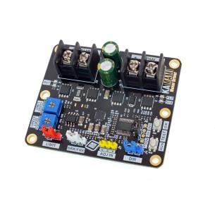
KAmod Motor Driver to zaawansowany sterownik silnika DC zasilany napięciem 6-30 V, umożliwiający regulację mocy metodą PWM oraz kontrolę kierunku obrotów, kompatybilny z sygnałami analogowymi i PWM z różnych źródeł, wyposażony w zabezpieczenia przeciążeniowe i termiczne oraz funkcje łagodnego startu i zatrzymania
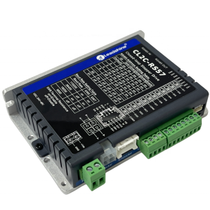
Zaawansowany sterownik silnika krokowego Nema 23 z serii CLRS, zaprojektowany do precyzyjnych zastosowań przemysłowych z komunikacją sieciową RS485 (Modbus RTU). Eliminuje ryzyko utraty kroków dzięki zamkniętej pętli sprzężenia zwrotnego i oferuje wsparcie dla trybów: pozycjonowania (Profile Position), prędkości (Velocity), powrotu do pozycji referencyjnej (Homing) oraz PR Mode z 16-pozycyjną tabelą sterowania punkt-do-punktu. Sterownik obsługuje do 31 osi w jednej sieci, oferuje prąd do 7 A, napięcie zasilania od 20 do 50 VDC i chłodzenie pasywne lub aktywne, co czyni go niezawodnym rozwiązaniem dla robotyki, automatyki i systemów CNC. CL2C-RS57
Brak towaru
Kompaktowy sterownik, który umożliwia precyzyjne sterowanie bipolarnymi silnikami krokowymi. Oferuje dużą precyzję ruchu dzięki możliwości sterowania silnikiem krokowym z rozdzielczością do 1/128 kroku oraz dwa interfejsy sterujące - sterowanie krokowe typu clock-in oraz komendy szeregowe. SparkFun ROB-25167
Kompaktowy i wydajny moduł przeznaczony do precyzyjnego sterowania bipolarnymi silnikami krokowymi, oferujący mikrostepping do 1/32 kroku oraz maksymalny prąd do 2 A w trybie szczytowym. Dzięki zaawansowanym funkcjom, takim jak algorytm QuietStep (APFD), wbudowane zabezpieczenia oraz kompatybilność pinowa z A4988, doskonale sprawdzi się w projektach hobbystycznych, edukacyjnych i przemysłowych. Wersja Blue Edition z czterowarstwową płytką i miedzią 2 oz zapewnia lepsze odprowadzanie ciepła, zwiększając niezawodność pracy nawet przy wyższych obciążeniach. Pololu 5340
Kompaktowy i wydajny moduł przeznaczony do precyzyjnego sterowania bipolarnymi silnikami krokowymi, oferujący mikrostepping do 1/32 kroku oraz maksymalny prąd do 2 A w trybie szczytowym. Dzięki zaawansowanym funkcjom, takim jak algorytm QuietStep (APFD), wbudowane zabezpieczenia oraz kompatybilność pinowa z A4988, doskonale sprawdzi się w projektach hobbystycznych, edukacyjnych i przemysłowych. Wersja Blue Edition z czterowarstwową płytką i miedzią 2 oz zapewnia lepsze odprowadzanie ciepła, zwiększając niezawodność pracy nawet przy wyższych obciążeniach. Pololu 5341
Sterownik do bipolarnych silników krokowych z interfejsem STEP/DIR, mikrokroki do 1/16 oraz regulacja prądu za pomocą potencjometru, współpraca z logiką 3,3 V i 5 V, wersja bez przylutowanych złączy. Pololu 5342
Sterownik do bipolarnych silników krokowych z interfejsem STEP/DIR, mikrokroki do 1/16 oraz regulacja prądu za pomocą potencjometru, współpraca z logiką 3,3 V i 5 V, przylutowane złącza goldpin. Pololu 5343
Sterownik do bipolarnych silników krokowych z interfejsem STEP/DIR, mikrokroki do 1/16 oraz maksymalny prąd do 1,5 A przy 5 V lub 1 A przy 3,3 V, wersja bez przylutowanych złączy. Pololu 5344
Sterownik do bipolarnych silników krokowych z interfejsem STEP/DIR, mikrokroki do 1/16, przylutowane złącza goldpin oraz maksymalny prąd do 1,5 A przy 5 V lub 1 A przy 3,3 V. Pololu 5345
Sterownik do bipolarnych silników krokowych z interfejsem STEP/DIR, mikrokroki do 1/16 oraz maksymalny prąd do 1 A przy logice 5 V lub 660 mA przy 3,3 V. Pololu 5346
Sterownik silnika krokowego oparty na układzie A5984, z przylutowanymi złączami goldpin, przeznaczony do sterowania bipolarnymi silnikami krokowymi w projektach elektronicznych i robotycznych. Pololu 5347
Sterownik silnika krokowego A5984 do silników bipolarnych, zasilanie 8–40 V, stały limit prądu 750 mA przy 5 V lub 500 mA przy 3,3 V, mikrokrok do 1/32 oraz interfejs STEP/DIR. Pololu 5348
Sterownik silnika krokowego A5984 do silników bipolarnych, zasilanie 8–40 V, stały limit prądu 750 mA przy 5 V lub 500 mA przy 3,3 V, mikrokrok do 1/32 oraz interfejs STEP/DIR. Wersja z przylutowanymi złączami goldpin. Pololu 5349
Sterownik silnika krokowego A5984 do silników bipolarnych, zasilanie 8-40 V, stały limit prądu 500 mA przy 5 V lub 330 mA przy 3,3 V, mikrokrok do 1/32 oraz interfejs STEP/DIR. Pololu 5350
Moduł pozwala na zmianę prędkości obrotowej silnika poprzez regulację PWM o częstotliowści do 500 kHz. Posiada wbudowane zabezpieczenie przed podaniem odwrotnej polaryzacji zasilania oraz zabezpieczenie termiczne. Pololu 2960