


179,91 zł Netto
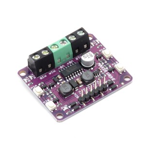
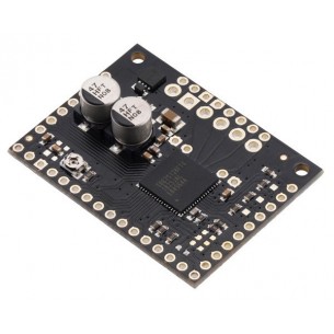
Pololu wysokoprądowy sterownik silnika umożliwia sterowanie silnikami DC o dużym poborze prądu w systemach do 40 V. Moduł sprawdza się w projektach wymagających wysokiej wydajności prądowej, prostego interfejsu sterowania oraz kompaktowej konstrukcji, przy zachowaniu elastyczności w doborze chłodzenia i zabezpieczeń. Pololu 759
Pololu High-Power Motor Driver 24v20 przeznaczony do dwukierunkowego sterowania jednym szczotkowym silnikiem prądu stałego o dużej mocy. Moduł oparty na dyskretnym mostku H z tranzystorami MOSFET typu N obsługuje szeroki zakres napięcia zasilania od 5,5 V do 40 V, co umożliwia zastosowanie w systemach 12 V, 24 V oraz innych instalacjach o podwyższonym napięciu.
Kompaktowa płytka o wymiarach 1,8 × 0,8 cala umożliwia dostarczanie do 20 A prądu ciągłego bez radiatora, a przy zastosowaniu dodatkowego chłodzenia nawet do około 28 A. Sterownik obsługuje tryby sign-magnitude oraz locked-antiphase, wymagając minimalnie dwóch linii sterujących (PWM i DIR), co upraszcza integrację z mikrokontrolerami i systemami sterowania.
Układ oferuje detekcję zwarć, spadków napięcia oraz przegrzania, sygnalizowanych na wyjściach FF1 i FF2. Moduł nie posiada sprzętowych zabezpieczeń nadprądowych ani temperaturowych, dlatego w aplikacjach pracujących blisko granic parametrów zalecane pozostaje stosowanie zewnętrznego pomiaru prądu oraz odpowiedniego chłodzenia. Rozwiązanie sprawdza się w robotach mobilnych, napędach o dużej mocy, platformach badawczych i projektach prototypowych.
Cechy
Producent BTC Korporacja sp. z o. o. Lwowska 5 05-120 Legionowo Polska sprzedaz@kamami.pl 22 767 36 20
Osoba odpowiedzialna BTC Korporacja sp. z o. o. Lwowska 5 05-120 Legionowo Polska sprzedaz@kamami.pl 22 767 36 20
Dwukanałowy sterownik silników DC zasilany napięciem od 2,5 do 9,5V o maksymalnym prądzie ciągłym 1A na kanał. Posiada wbudowany regulator napięcia. Cytron Maker Drive
Jednokanałowy sterownik silników DC umożliwiający sterowanie silnika napięciem z zakresu 7-30V oraz który pobiera prąd do 10A. Zestaw posiada potencjometr i przełącznik kierunku obrotów. Cytron MD10_POT
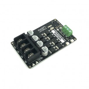
Jednokanałowy sterownik silnika DC umożliwiający sterowanie pracą silnika o napięciu zasilania z zakresu 6-30V oraz który pobiera prąd do 20A (chwilowo do 60A). Cytron MD20A
Brak towaru
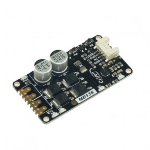
Jednokanałowy sterownik silników DC umożliwiający sterowanie silnika napięciem z zakresu 6-30V oraz prądem do 13A. Umożliwia sterowanie prędkością silnika z użyciem sygnały PWM. Cytron MD13S
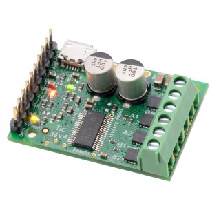
Moduł sterownika silnika krokowego TB67S128FTG zasilanego napięciem 6,5-44V i prądzie pracy 2,1A. Sterownik pozwala na kontrolowanie ruchu silnika aż z 8 różnymi rozdzielczościami (do 1/128 kroku). Pololu 2998
Sterownik silników pozwalający na sterowanie silnikiem krokowym o napięciu z zakresu 8-50V który pobiera maksymalny prąd do 4A (do 6 z dodatkowym chłodzeniem). Pololu 3141
Sterownik silników pozwalający na sterowanie silnikiem krokowym dużej mocy za pomocą komputera, mikrokontrolera lub aparatury RC. Pololu 3140
Brak towaru
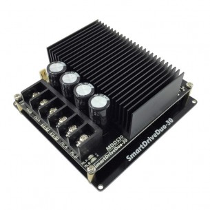
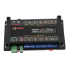
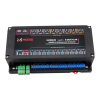
Dwukanałowy sterownik silników DC o napięciu pracy od 7 do 35 V i prądzie ciągłym do 30 A. Może być sterowany sygnałem analogowym, PWM, UART, RC lub za pomocą wbudowanych przycisków. Cytron MDDS30
Brak towaru
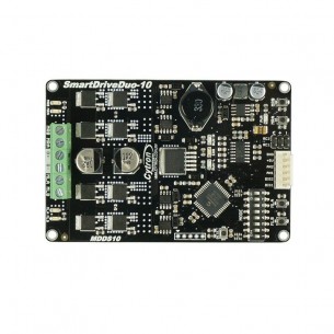
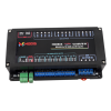
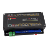
Dwukanałowy sterownik silników DC o napięciu pracy od 7 do 35 V i prądzie ciągłym do 10 A. Może być sterowany sygnałem analogowym, PWM, UART, RC lub za pomocą wbudowanych przycisków. Cytron MDDS10
Brak towaru
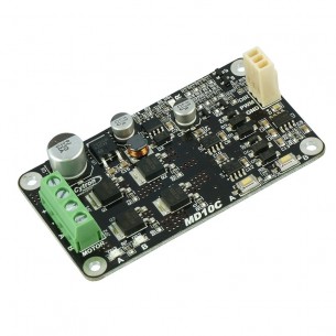
Sterownik silnika prądu stałego (DC) o napięciu pracy od 5 do 30 V i maksymalnym prądzie ciągłym do 13 A. Może być sterowany sygnałem PWM lub za pomocą wbudowanych przycisków. Cytron MD10C
Sterownik silnika prądu stałego (DC) o napięciu pracy od 5 do 30 V i maksymalnym prądzie ciągłym do 30 A. Może być sterowany sygnałem PWM lub za pomocą wbudowanych przycisków. Cytron MD30C
Brak towaru
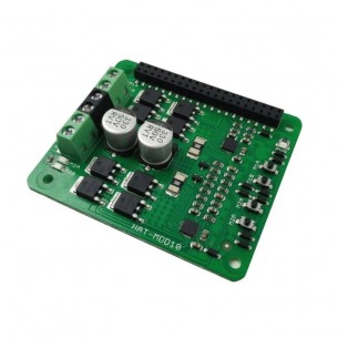
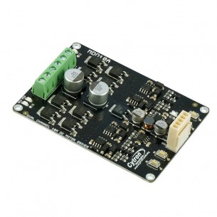
HAT z dwukanałowym sterownikiem silników DC dla Raspberry Pi. Ma napięcie pracy od 6 do 24 V i prąd ciągły do 10 A. Może być sterowany sygnałem PWM lub za pomocą wbudowanych przycisków. Cytron HAT-MDD10
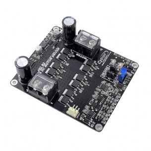
Dwukanałowy sterownik silników prądu stałego (DC) o napięciu pracy od 5 do 30 V i maksymalnym prądzie ciągłym do 10 A. Może być sterowany sygnałem PWM lub za pomocą wbudowanych przycisków. Cytron MDD10A
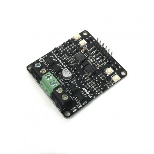
Dwukanałowy sterownik silników prądu stałego (DC) o napięciu pracy od 4 do 16 V i maksymalnym prądzie ciągłym do 3 A. Może być sterowany sygnałem PWM lub za pomocą wbudowanych przycisków. Cytron MDD3A
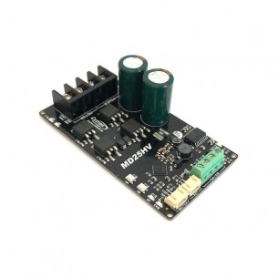
Sterownik silnika prądu stałego (DC) o napięciu pracy od 7 do 58 V i maksymalnym prądzie ciągłym do 25 A. Może być sterowany sygnałem PWM, potencjometrem lub za pomocą wbudowanych przycisków. Cytron MD25HV
Brak towaru
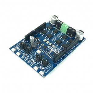
Shield z dwukanałowym sterownikiem silników DC dla Arduino. Ma napięcie pracy od 7 do 30 V i prąd ciągły do 10 A. Może być sterowany sygnałem PWM lub za pomocą wbudowanych przycisków. Cytron SHIELD-MDD10
Brak towaru
Pololu wysokoprądowy sterownik silnika umożliwia sterowanie silnikami DC o dużym poborze prądu w systemach do 40 V. Moduł sprawdza się w projektach wymagających wysokiej wydajności prądowej, prostego interfejsu sterowania oraz kompaktowej konstrukcji, przy zachowaniu elastyczności w doborze chłodzenia i zabezpieczeń. Pololu 759