


zł179.91 tax excl.
Pololu High-Power Motor Driver 24v20
Pololu High-Power Motor Driver 24v20
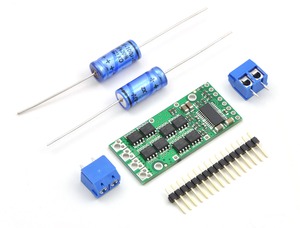
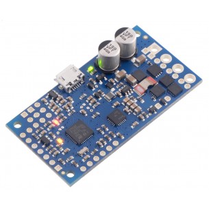
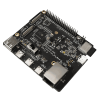
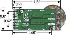
This discrete MOSFET H-bridge motor driver enables bidirectional control of one high-power DC brushed motor. The little 1.8×0.8-inch board supports a wide 5.5 to 40 V voltage range and is efficient enough to deliver a continuous 20 A without a heat sink.
 |
The Pololu high-power motor driver is a discrete MOSFET H-bridge designed to drive large DC brushed motors. The H-bridge is made up of two N-channel MOSFET per leg, and most of the board’s performance is determined by these MOSFETs (the rest of the board contains the circuitry to take user inputs and control the MOSFETs). The MOSFET datasheet is available under the “Resources” tab. The MOSFETs have an absolute maximum voltage rating of 40 V, and higher voltages can permanently destroy the motor driver. Under normal operating conditions, ripple voltage on the supply line can raise the maximum voltage to more than the average or intended voltage, so a safe maximum voltage is approximately 34 V.
Note: Charged battery voltages can be much higher than nominal voltages, so the maximum nominal battery voltage we recommend is 28 V unless appropriate measures are taken to limit the peak voltage.
The versatility of this driver makes it suitable for a large range of currents and voltages: it can deliver up to 20 A of continuous current with a board size of only 1.8" by 0.8" and no required heat sink. With the addition of a heat sink, it can drive a motor with up to about 28 A of continuous current. The module offers a simple interface that requires as little as two I/O lines while allowing for both sign-magnitude and locked-antiphase operation. Integrated detection of various short-circuit conditions protects against common causes of catastrophic failure; however, please note that the board does not include reverse power protection or any over-current or over-temperature protection.
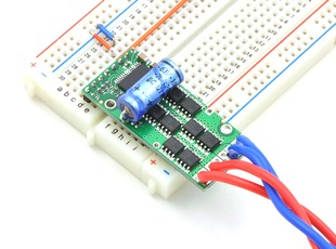
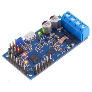
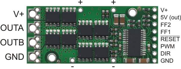
The motor and motor power connections are on one side of the board, and the control connections (5V logic) are on the other side. The motor supply should be capable of supplying high current, and a large capacitor should be installed close to the motor driver. The included axial capacitors can be installed directly on the board in the pins labeled '+' and '-' as shown below. Such installations are compact but might limit heat sinking options; also, depending on the power supply quality and motor characteristics, a larger capacitor might be required. There are two options for connecting to the high-power signals (V+, OUTA, OUTB, GND): large holes on 0.2" centers, which are compatible with the included terminal blocks, and pairs of 0.1"-spaced holes that can be used with perfboards, breadboards, and 0.1" connectors.
Warning: Take proper safety precautions when using high-power electronics. Make sure you know what you are doing when using high voltages or currents! During normal operation, this product can get hot enough to burn you. Take care when handling this product or other components connected to it.
The logic connections are designed to interface with 5V systems (5.5 V max); the minimum high input signal threshold is 3.5 V, so we do not recommend connecting this device directly to a 3.3 V controller. In a typical configuration, only PWM and DIR are required. The two fault flag pins (FF1 and FF2) can be monitored to detect problems (see the Fault Flag Table below for more details). The RESET pin, when held low, puts the driver into a low-power sleep mode and clears any latched fault flags. The V+ pin on the logic side of the board gives you access to monitor the motor’s power supply (it should not be used for high current). The board also provides a regulated 5 V pin which can provide a few milliamps (this is typically insufficient for a whole control circuit but can be useful as a reference or for very low-power microcontrollers).
 |
| PIN | Default State | Description |
|---|---|---|
| V+ | This is the main 5.5 – 30 V motor power supply connection, which should typically be made to the larger V+ pad. The smaller V+ pads along the long side of the board are intended for power supply capacitors, and the smaller V+ pad on the logic side of the board gives you access to monitor the motor’s power supply (it should not be used for high current). | |
| 5V (out) | This regulated 5V output provides a few milliamps. This output should not be connected to other external power supply lines. Be careful not to accidentally short this pin to the neighboring V+ pin while power is being supplied as doing so will instantly destroy the board! | |
| GND | Ground connection for logic and motor power supplies. | |
| OUTA | A motor output pin. | |
| OUTB | B motor output pin. | |
| PWM | LOW | Pulse width modulation input: a PWM signal on this pin corresponds to a PWM output on the motor outputs. |
| DIR | FLOAT | Direction input: when DIR is high current will flow from OUTA to OUTB, when it is low current will flow from OUTB to OUTA. |
| RESET | HIGH | The reset pin, when pulled low, puts the board into a low-power sleep mode and clears any latched fault flags. |
| FF1 | LOW | Fault flag 1 indicator: FF1 goes high when certain faults have occurred. See table below for details. |
| FF2 | LOW | Fault flag 2 indicator: FF2 goes high when certain faults have occurred. See table below for details. |
A 16-pin straight breakaway male header, two 100 uF capacitors, and two 2-pin 5mm terminal blocks are included with each motor driver. (Note: The terminals blocks are only rated for 15 A; for higher power applications, use thick wires soldered directly to the board.) Connecting large capacitors across the power supply is recommended; one way to do it is between the '+' and '-' holes, as shown below. The two mounting holes are intended to be used with #2 screws (not included).
|
|
With the PWM pin held low, both motor outputs will be held low (a brake operation). With PWM high, the motor outputs will be driven according to the DIR input. This allows two modes of operation: sign-magnitude, in which the PWM duty cycle controls the speed of the motor and DIR controls the direction, and locked-antiphase, in which a pulse-width-modulated signal is applied to the DIR pin with PWM held high.
In locked-antiphase operation, a low duty cycle drives the motor in one direction, and a high duty cycle drives the motor in the other direction; a 50% duty cycle turns the motor off. A successful locked-antiphase implementation depends on the motor inductance and switching frequency smoothing out the current (e.g. making the current zero in the 50% duty cycle case), so a high PWM frequency might be required.
| Motor Driver Truth Table | ||||
|---|---|---|---|---|
| PWM | DIR | OUTA | OUTB | Operation |
| H | L | L | H | Forward |
| H | H | H | L | Backward |
| L | X | L | L | Brake |
The motor driver supports PWM frequencies as high as 40 kHz, though higher frequencies result in higher switching losses in the motor driver. Also, the driver has a dead time (when the outputs are not driven) of approximately 3 us per cycle, so high duty cycles become unavailable at high frequencies. For example, at 40 kHz, the period is 25 us; if 3 us of that is taken up by the dead time, the maximum available duty cycle is 22/25, or 88%. (100% is always available, so gradually ramping the PWM input from 0 to 100% will result in the output ramping from 0 to 88%, staying at 88% for inputs of 88% through 99%, and then switching to 100%.)
The motor driver can tolerate peak currents in excess of 200 A. The peak current ratings are for quick transients (e.g. when a motor is first turned on), and the continuous rating of 25 A is dependent on various conditions, such as the ambient temperature. The main limitation comes from heating and power dissipation; therefore, at high currents, the motor driver will be extremely hot, and performance can be improved by adding heat sinks or otherwise cooling the board. The driver’s printed circuit board is designed to draw heat out of the MOSFETs, but performance can be improved by adding a heat sink. With a proper heat sink, the motor driver can deliver up to 28 A of continuous current. For more information on power dissipation see the data sheet for the MOSFETs on the Resources tab.
Because there is no internal temperature limiting on the motor driver, the entire system should be designed to keep the load current below the 20 A limit. An easy way to achieve this is to select a motor with a stall current below that limit. However, because a good motor can have stall currents dozens of times higher than the typical operating current, motors with stall currents that are hundreds of amps can be used with this driver as long as the running current is kept low. For example, a motor with a 80 A stall current might run well at 8 A, leaving a safe margin for the current to double for several minutes at a time or to triple for several seconds. If the motor does stall completely for a prolonged period, however, the motor or driver are likely to burn out.
Warning: This motor driver has no over-current or over-temperature shut-off. Either condition can cause permanent damage to the motor driver. You might consider using an external current sensor, such as our ACS714 ±30A bidirectional current sensor carrier to monitor your current draw.
The motor driver can detect three different fault states, which are reported on the FF1 and FF2 pins. The detectable faults are short circuits on the output, under-voltage, and over-temperature. A short-circuit fault is latched, meaning the outputs will stay off and the fault flag will stay high, until the board is reset (RESET brought low). The under-voltage fault disables outputs but is not latched. The over-temperature fault provides a weak indication of the board being too hot, but it does not directly indicate the temperature of the MOSFETs, which are usually the first components to overheat. The fault flag operation is summarized below.
| Flag State | Fault Description | Disable Outputs | Latched Until Reset | |
|---|---|---|---|---|
| FF1 | FF2 | |||
| L | L | No fault | No | No |
| L | H | Short Circuit | Yes | Yes |
| H | L | Over Temperature | No | No |
| H | H | Under Voltage | Yes | No |
There are currently nine versions of the high-power motor driver. The three CS versions have the same pinout, and the six non-CS versions have the same pinout. The following table provides a comparison of the high-power motor drivers:
| Pololu high-power motor drivers | ||
|---|---|---|
| Name | Max nominal battery voltage (V) | Max continuous current (A) w/o heat sink |
| High-power motor driver 18v25 CS | 18 | 25 |
| High-power motor driver 18v25 | 18 | 25 |
| High-power motor driver 18v15 | 18 | 15 |
| High-power motor driver 24v23 CS | 28 | 23 |
| High-power motor driver 24v20 | 28 | 20 |
| High-power motor driver 24v12 | 28 | 12 |
| High-power motor driver 36v20 CS | 36 | 20 |
| High-power motor driver 36v15 | 36 | 15 |
| High-power motor driver 36v9 | 36 | 9 |
Note: Please consider our Simple Motor Controllers as alternatives to these motor drivers. They have very similar power characteristics and offer high-level interfaces (e.g. USB, RC hobby servo pulses, analog voltages, and TTL serial commands) that make them much easier to use for many applications.
Data sheet
Manufacturer BTC Korporacja sp. z o. o. Lwowska 5 05-120 Legionowo Poland sprzedaz@kamami.pl 22 767 36 20
Responsible person BTC Korporacja sp. z o. o. Lwowska 5 05-120 Legionowo Poland sprzedaz@kamami.pl 22 767 36 20
Dual DC motor controller designed for Arduino, which enables the motor to be supplied with voltage in the 4.5 ... 28V range and power consumption in continuous operation of 2.6 A (5A at the top) of two DC motors. Polol 2520
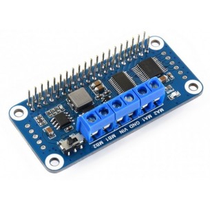
Dual DC motor controller designed for Raspberry Pi, which enables the engine to be supplied with voltage in the 4.5-28V range and power consumption in continuous operation of 2.6A (5A in peak) of two DC motors. Pololu 2762
Dual DC motor controller designed for Raspberry Pi, which enables the engine to be supplied with voltage in the 4.5-28V range and power consumption in continuous operation of 2.6A (5A in peak) of two DC motors. Self-assembly set. Pololu 2761
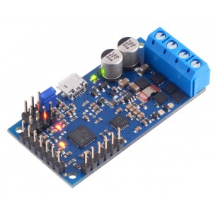
DC motor driver with voltage 4.5..28V and maximum continuous current of 2.6A. It has the ability to easily implement the feedback loop and numerous control interfaces. Polol 3143
No product available!
DC motor driver with voltage 4.5..28V and maximum continuous current of 2.6A. It has the ability to easily implement the feedback loop and numerous control interfaces. Polol 3142
No product available!
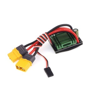
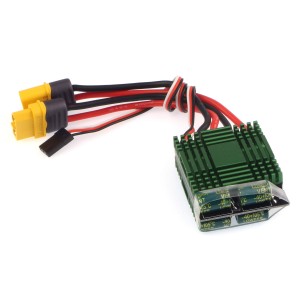
Bi-directional ESC speed controller for brush motors. It can deliver 20 A and has cables terminated with an XT60 connector. DFRobot DRI0047
The brakeless bidirectional speed controller (ESC) is an advanced brushed motor control device that offers up to 40 A continuous current and up to 340 A peak current, ensuring stable operation and dynamic load response. PPM signal control allows precise control of the motor speed and direction, while the radiator and XT60 connector ensure safe use and effective cooling.
No product available!
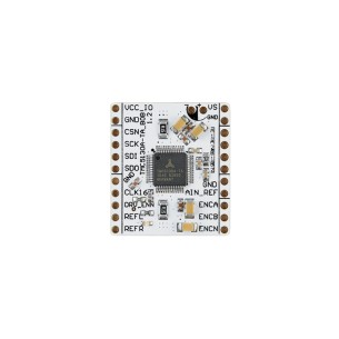
TMC5130A-BOB enables convenient testing and integration of stepper motor control in applications requiring precise positioning and motion control. Integrated ramping functions, microstep interpolation, and encoder support make it an ideal choice for automation, robotics, and mechatronic systems.
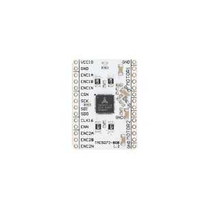
TMC5072-BOB is a compact breakout board featuring the TMC5072 IC, designed for rapid prototyping of precision motion-control applications. High microstepping resolution, encoder support and a wide supply voltage range make it suitable for projects such as 3D printers, CNC axis controllers and robotic manipulators.
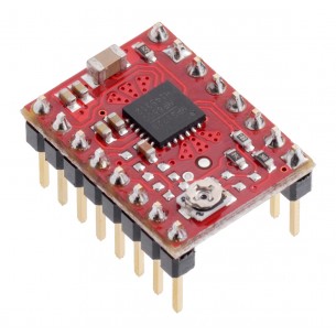
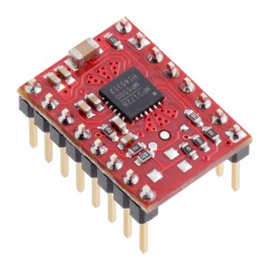
Stepper motor driver with MP6500 system with a potentiometer for current regulation. It allows the bipolar motor to be supplied with current up to 1.5A per phase without the use of a heat sink. Pololu 2967
No product available!
The stepper motor driver with the MP6500 system, allows the bipolar motor to be supplied with a current of up to 2A per phase, without the use of a heat sink. The system can be supplied with voltage in the range 4.5 ... 35V. Polol 2969
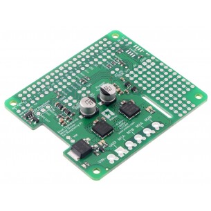
HAT with TB6612FNG engine controller and PCA9685 PWM controller designed for Raspberry Pi minicomputers. The board is equipped with a 40-pin connector characteristic of Raspberry Pi, making it compatible with all minicomputers with this connector. Waveshare Motor Driver HAT
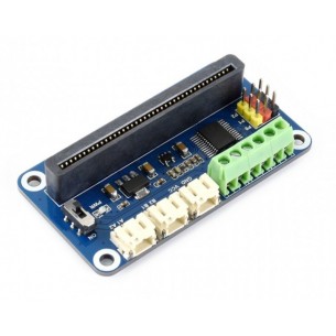
The expansion module is designed to work with the micro:bit educational board. It can control 3 servos and 2 DC motors. Waveshare Motor Driver for micro:bit
No product available!
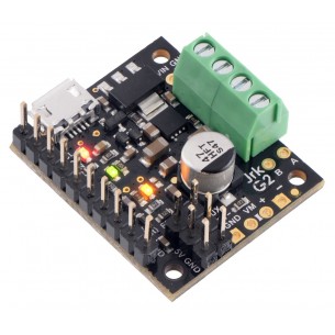
Pololu G2 18v15 High Power is a miniature DC motor controller. Power supply for the controller: 6.5 ... 30 V. Current efficiency of the module: 15 A. The module has protection against back voltage and overvoltages. Pololu 1362
No product available!
Pololu G2 18v15 High Power is a miniature DC motor controller. Power supply for the controller: 6.5 ... 30 V. Current efficiency of the module: 15 A. The module has protection against back voltage and overvoltages. Pololu 1363
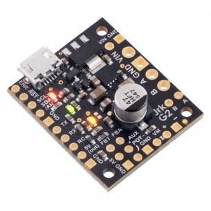
Pololu G2 24v12 High Power is a miniature DC motor controller. Driver\'s power supply: 6.5 ... 30V. Current capacity of the module: 12A. The module has protection against back voltage and overvoltage. Pololu 1364
Pololu High-Power Motor Driver 24v20