


zł109.55 tax excl.
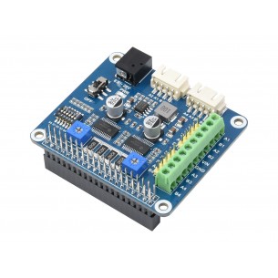
VNH5019 Motor Driver Carrier
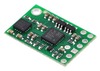
VNH5019 Motor Driver Carrier
This carrier board for ST’s VNH5019 motor driver IC operates from 5.5 to 24 V and can deliver a continuous 12 A (30 A peak). It works with 2.5 to 5 V logic levels, supports ultrasonic (up to 20 kHz) PWM, and features current sense feedback (an analog voltage proportional to the motor current). Along with built-in protection against reverse-voltage, over-voltage, under-voltage, over-temperature, and over-current, these features make this product a great general-purpose motor driver.
 |
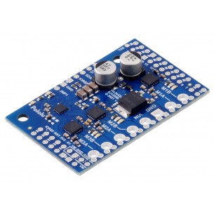
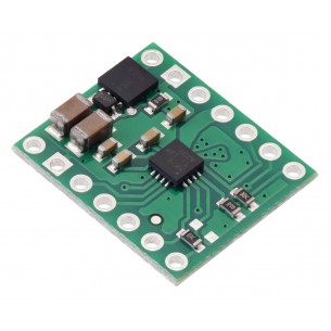
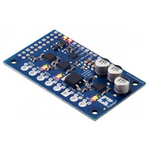
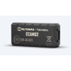
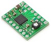
| VNH5019 motor driver carrier, bottom view with dimensions. |
|---|
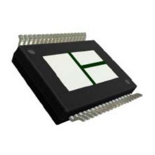
This module is a compact breakout board for ST’s high-power VNH5019 motor driver IC, a fully integrated H-bridge that can be used for bidirectional speed control of a single brushed DC motor. The basic operation of the driver is summarized below, but we also recommend careful reading of the VNH5019 datasheet (629k pdf) before using this product. The board incorporates most of the components of the typical application diagram on page 14 of the VNH5019 datasheet, including pull-up and current-limiting resistors and a FET for reverse battery protection. It ships fully populated with its SMD components, including the VNH5019, as shown in the product picture.
1 While the overvoltage protection typically kicks in at 27 V, it can trigger at voltages as low as 24 V, so we do not recommend using this motor driver with 24 V batteries, which significantly exceed 24 V when fully charged.
The motor and motor power connections are on one side of the board and the control connections are on the other side. The motor power supply connects to the large VIN and GND pins; it should be between 5.5 and 24 V and have the ability to deliver the potentially high currents the motor will require. The logic power supply (typically 2.5 – 5 V) connects to the small VDD and GND pads on the control side of the board and is used to power the internal pull-ups on the ENA and ENB enable lines. Any control input voltage above 2.1 V is guaranteed to be high, so this driver can be directly interfaced into both 3.3 and 5 V systems.
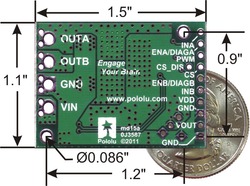
The following diagram shows the minimum connections required for interfacing this motor driver with a microcontroller:
 |
| Minimal wiring diagram for connecting a microcontroller to a VNH5019 motor driver carrier. |
|---|
In this configuration, motor direction is determined by the states of the INA and INB pins and motor speed is controlled by the duty cycle of a PWM signal supplied to the driver’s PWM pin. The PWM pin is pulled low on the board, so the motor driver outputs are effectively disabled by default; the INA and INB pins are floating (they are not pulled to any particular default voltage). See the truth tables in the VNH5019A-E datasheet for more information on how the INA, INB, and PWM pins affect the driver outputs, OUTA and OUTB. Note that it is also possible to save a microcontroller I/O line by directly PWMing the INA and INB pins while holding the PWM pin high (e.g. by connecting it directly to VDD).
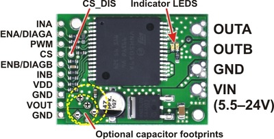
This board features motor indicator LEDs that can be used to test that motor driver outputs are working as expected before actually connecting a motor (this can be especially helpful in detecting problems due to insufficient power supplies). The LED brightness with increase with motor speed, and the LED color changes with direction.
 |
| PIN | Default State | Description |
|---|---|---|
| VIN | The connection point for the positive side of the 5.5 – 24 V motor power supply. Since the overvoltage protection can be as low as 24 V, we do not recommend using 24V batteries for VIN. | |
| VDD | The connection point for the positive side of the logic power supply (typically 2.5 – 5 V). The only function of this pin is to power the internal pull-ups on the two enable lines, ENA and ENB. | |
| VOUT | This pin gives you access to the motor power supply after the reverse-voltage protection MOSFET (see the board schematic below). It can be used to supply reverse-protected power to other components in the system, but it should not be used for high currents. This pin should only be used as an output. | |
| GND | Ground connection points for logic and motor power supplies. The control source and the motor driver must share a common ground. | |
| OUTA | Output of half-bridge A (connects to one terminal of a DC motor). | |
| OUTB | Output of half-bridge B (connects to the other terminal of a DC motor). | |
| PWM | LOW | Pulse width modulation input: a PWM signal on this pin corresponds to a PWM output on the motor outputs. |
| INA | FLOAT | Motor direction input A (“clockwise” input). |
| INB | FLOAT | Motor direction input B (“counterclockwise” input). |
| CS | Current sense output. The pin voltage is roughly 140 mV per amp of output current when the CS_DIS pin is low or disconnected. The current sense reading is more accurate at higher currents. (Note that while the CS voltage can potentially exceed 3 V at high currents, the current sense circuit is safe for use with 3V analog inputs. The MCU’s analog input voltage will be clamped to a safe value by its protection diode, and only a few hundred microamps at most will flow through that diode.) | |
| ENA/DIAGA | HIGH | Combination enable input/diagnostic output for half-bridge A. When the driver is functioning normally, this pin acts as an enable input, with a logical high enabling half-bridge A and a logical low disabling half-bridge A. When a driver fault occurs, the IC drives this pin low and half-bridge A is disabled. This pin is connected to VDD through a pull-up resistor on the board. |
| ENB/DIAGB | HIGH | Combination enable input/diagnostic output for half-bridge B. See the description of ENA/DIAGA. |
| CS_DIS | LOW | Disables the current sense output, CS, when high. Can be left disconnected in most applications. |
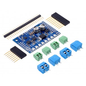
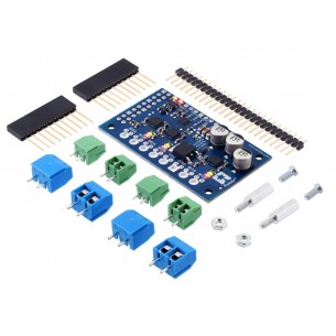
A 20-pin 0.1? straight breakaway male header and two 2-pin 5mm terminal blocks are included with the motor driver as shown in the picture below. You can use the terminal blocks to make your motor and motor power connections, or you can break off an 8?1 section of the 0.1? header strip and solder it into the smaller through-holes that border the four large motor and motor power pads. Note, however, that the terminal blocks are only rated for 16 A, and each header pin pair is only rated for a combined 6 A, so for higher-power applications, thick wires should be soldered directly to the board.
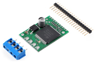 |
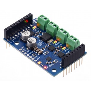
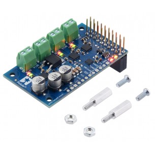
| VNH5019 motor driver carrier with included hardware. |
|---|
Soldering the 0.1? headers to the logic connections enables use with custom cables or solderless breadboards, or wires can be soldered directly to the board for more compact installations. Motor and motor power connections should not be made through a breadboard.
The motor driver includes a 47 uF electrolytic power capacitor, and there is room to add additional capacitors (e.g. to compensate for long power wires or increase stability of the power supply). Additional power capacitors are usually not necessary, and no additional capacitors are included with this motor driver.
The two mounting holes are intended for use with #2 screws (not included).
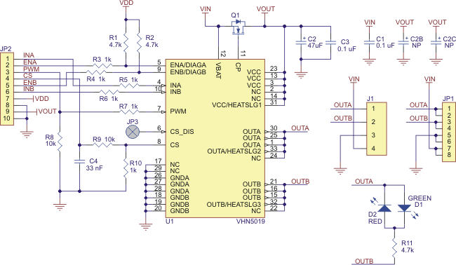 |
| Schematic diagram for the Pololu VNH5019 motor driver carrier. |
|---|
This schematic is also available as a downloadable pdf: VNH5019 carrier schematic (34k pdf)
Note: All boards shipped from Pololu prior to October 28, 2011 have 1.5k current sense resistors (R10 in the schematic above), which results in a current sense (CS) output of approximately 210 mV/A. That resistor has now been changed to 1k for better compatibility with 3V systems, producing a CS output of approximately 140 mV/A.
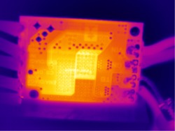 |
| Thermal image of the underside of the VNH5019 motor driver carrier during one of our current tests. |
|---|
In addition to this VNH5019 carrier, we offer carrier boards for two similar, older motor drivers from ST: the VNH3SP30 and the VNH2SP30. The VNH5019 is the only one of the three with a practical operating voltage above 16 V, and it is the only one that works with 3 V logic.
The current-related values in the table below (i.e. the entries to which footnote 3 applies) are the results of tests on only one or two of each driver version, so they do not capture potential unit-to-unit variation. As such, the values should be treated as rough estimates of performance, not as performance guarantees. While these tests seem to indicate that the VNH2SP30 runs a bit cooler—and hence can deliver more continuous current—than the VNH5019, it is important to note that the three driver versions were tested at different times under potentially different conditions, so the results are not necessarily accurate indications of relative performance.
In our tests, we noticed that the thermal protection on the VNH5019 was activating at a lower temperature (153°C) than on the VNH2SP30 (170°C), which could partially account for the shorter VNH5019 overheating times. However, we also observed that the VNH5019 was reaching slightly higher temperatures than the VNH2SP30 when used under the same conditions: the VNH5019 reached a temperature of 85°C after 3 minutes at 10 A while the VNH2SP30 reached a temperature of 80°C.
The following table offers a comparison of the three drivers:
| VNH3SP30 | VNH2SP30 | VNH5019 | |
|---|---|---|---|
| Operating voltage: (1) | 5.5 – 16 V (2) | 5.5 – 16 V | 5.5 – 24 V |
| MOSFET on-resistance (per leg): | 34 mΩ typ. | 19 mΩ max. | 18 mΩ typ. |
| Max PWM frequency | 10 kHz | 20 kHz | 20 kHz |
| Current sense | n/a | 0.13 V/A typ. | 0.14 V/A typ. |
| Over-voltage shutoff | 36 V min. (2) / 43 V typ. | 16 V min. / 19 V typ. | 24 V min. / 27 V typ. |
| Logic input high threshold | 3.25 V min. | 3.25 V min. | 2.1 V min. |
| Time to overheat at 20 A (3) | 8 s | 35 s | 20 s |
| Time to overheat at 15 A (3) | 30 s | 150 s | 90 s |
| Current for infinite run time (3) | 9 A | 14 A | 12 A |
1 The VNH3SP30 can survive input voltages up to 40 V, and the VNH2SP30 and VNH5019 can survive input voltages up to 41 V, but the over-voltage shutoff will kick in at lower voltages.
2 While VNH3SP30’s over-voltage shutoff doesn’t activate until 36 V, in our experience, shoot-through currents make PWM operation impractical above 16 V.
3 Typical results using the Pololu motor driver carrier boards with 100% duty cycle at room temperature (with no forced airflow or heat sinking beyond the carrier PCB).
The motor driver IC has a maximum continuous current rating of 30 A. However, the chips by themselves will overheat at lower currents (see the table above for typical values). The actual current you can deliver will depend on how well you can keep the motor driver cool. The carrier’s printed circuit board is designed to draw heat out of the motor driver chips, but performance can be improved by adding a heat sink. In our tests, we were able to deliver short durations (on the order of milliseconds) of 30 A and several seconds of 20 A without overheating. At 6 A, the chip gets just barely noticeably warm to the touch. For high-current installations, the motor and power supply wires should also be soldered directly instead of going through the supplied terminal blocks, which are rated for up to 16 A.
This product can get hot enough to burn you long before the chip overheats. Take care when handling this product and other components connected to it.
Many motor controllers or speed controllers can have peak current ratings that are substantially higher than the continuous current rating; this is not the case with these motor drivers, which have a 30 A continuous rating and over-current protection that can kick in as low as 30 A (50 A typical). Therefore, the stall current of your motor should not be more than 30 A. (Even if you expect to run at a much lower average current, the motor can still draw short bursts of high currents, such as when it is starting, if special steps are not taken.)
Note: The datasheet refers to the motor driver IC by the full part number VNH5019A-E, but the “A” seems to simply indicate that it was packaged in tubes. It mentions VNH5019TR-E as another valid part number for this IC (indicating tape-and-reel packaging).
 |
MinIMU-9 Gyro, Accelerometer, and Compass (L3G4200D and LSM303DLM Carrier) |
 |
Pololu Dual VNH5019 Motor Driver Shield for Arduino |
 |
A4988 Stepper Motor Driver Carrier |
Data sheet
Manufacturer BTC Korporacja sp. z o. o. Lwowska 5 05-120 Legionowo Poland sprzedaz@kamami.pl 22 767 36 20
Responsible person BTC Korporacja sp. z o. o. Lwowska 5 05-120 Legionowo Poland sprzedaz@kamami.pl 22 767 36 20
No product available!
DC motor driver that allows you to control the movement of three drives using the I2C interface. The set includes only the board without connectors. Pololu 5032
No product available!
DC motor driver that allows you to control the movement of three drives using the I2C interface. Plate with connectors for assembly. Pololu 5031
No product available!
DC motor driver that allows you to control the movement of three drives using the I2C interface. Board with soldered connectors. Pololu 5030
No product available!
Module with DC motor driver DRV8876. It can work with motors supplied with the voltage from 4.5 to 37 V and current consumption up to 1.1 A. Pololu 4037
Module with DC motor driver DRV8876. It can work with motors supplied with the voltage from 4.5 to 37 V and the current consumption up to 1.3 A. Pololu 4036
Module with DC motor driver DRV8874. It can work with motors supplied with the voltage from 4.5 to 37 V and current consumption up to 2.1 A. Pololu 4035
DC motor driver that allows you to control the movement of three drives using the I2C interface. Board with soldered connectors. Pololu 5033
DC motor driver that allows you to control the movement of three drives using the I2C interface. Connectors for self-assembly. Pololu 5034
DC motor driver that allows you to control the movement of three drives using the I2C interface. Pololu 5035
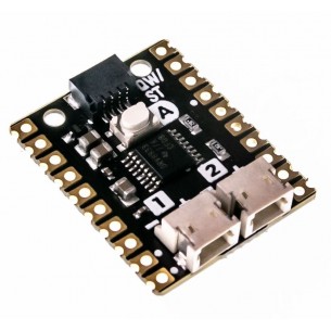
A module with a two-channel DC motor driver based on the TB6612FNG system. Designed for Wemos D1 Mini
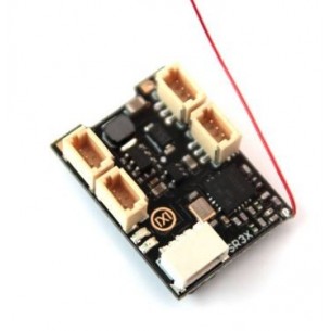
The bidirectional ESC controller enables precise control of brushed DC motors within a voltage range equivalent to 1S–2S Li-Ion/Li-Po packs. Its small size and compatibility with classic RC signals facilitate applications in compact mobile designs and robotic projects with limited mounting space
No product available!
The ESC RC controller module is designed for brush motors with a supply voltage from 3.5 to 6 V and a capacity of 1 A
ESC RC controller module with FlySky receiver designed for two brush motors with a supply voltage from 2.5 to 5 V and a current consumption of 2 A
No product available!
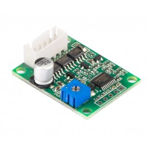
Brushless DC motor (BLDC) driver. It can operate motors powered with a voltage from 6 to 20 V with a current consumption of up to 3 A
Module with 2-channel DC motor driver DRV8833 designed to work with the Raspberry Pi Pico. It can work with a voltage from 2.7 to 10.8 V and a current of up to 1.2 A. Pimoroni PIM617
Extension module with a driver for two stepper motors based on the HR8825 system. Dedicated for Raspberry Pi minicomputers. Waveshare Stepper Motor HAT (B)
VNH5019 Motor Driver Carrier