
- Out-of-Stock


Introduction
Limitations of the DesignLab test version
Hardware and system requirements
Chapter 1. Installation of DesignLab programs in Windows 95
Chapter 2. First steps - analysis and optimization of the active filter
2.1. System description
2.2. Drawing a circuit in the Schematics program
2.3. AC analysis
2.4. Parametric analysis
2.5. Optimization task
Chapter 3. Schematics program - schematic editor
3.1. Toolbar commands
3.1.1. File commands
3.1.2. Edit commands
3.1.3. Draw commands
3.1.4. Navigate commands
3.1.5. View commands
3.1.6. Options commands
3.1.7. Analysis commands
3.1.8. Tools commands
3.1.9. Markers commands
3.1.10. Window commands
3.1.11. Help commands
3.2. Description of the function key commands
3.3. The appearance of the global window
3.4. Creating a circuit
Chapter 4. The Probe program
4.1. outfit
4.2. Application of function keys
4.3. Toolbar commands
4.3.1. Commands on the File menu toolbar
4.3.2. Edit commands
4.3.3. Trace commands
4.3.4. Plot commands
4.3.5. View commands
4.3.6. Tools commands
4.3.7. Window commands
4.3.8. Help commands
Chapter 5. The Pspice A / D program
Chapter 6. Defining analyzes
6.1. AC analysis
6.1 1. AC current analysis of a transistor amplifier
6.1.2. Analysis of the 4th order RLC filter
6.2. DC constant current analysis
6.2.1. DC voltage stabilizer analysis
6.2.2. Constant current analysis of a window discriminator
6.3. Time analysis - Transient
6.3.1. Triangle and rectangular waveform generator
6.4. Temperature analysis
6.5. Parametric analysis
6.5.1. Transistor amplifier
6.5.2. Generator with a T-double system
6.5.3. Voltage stabilizer with LM340-5 circuit
6.6. Sensitivity analysis
6.7. Fourier analysis
6.8. FFT analysis
6.9. Statistical analyzes
6.9.1. Worst Case analysis
6.9.2. Monte Carlo analysis
6.10. Simulation of digital circuits
6.10.1. Creating a layout
6.10.2. Converter analysis
6.10.3. Design and analysis of the modulo 7 meter
Chapter 7. Description of the PSpice Optimizer program
7.1. Introduction
7.2. Terminology
7.3. Manual optimization process
7.4. Automatic optimization
7.5. Optimization rules
7.6. Appeal to PSpice Optimizer
7.7. Connection with the DesignLab environment
7.8. General principles of designing in PSpice Optimizer
7.9. Rectifier with Graetz bridge
7.9.1. Transformer model
7.9.2. Selection of transformer ratio
7.9.3. Study of the influence of GAIN element amplification on the output voltage of the transformer
7.9.4. The optimization process
7.9.5. Checking the result of the optimization
7.9.6. Selection of serial diode resistance
7.10. Relaxation generator with time system 555
7.10.1. Construction of the system
7.10.2. The optimization process
Chapter 8. Symbol editor
8.1. Toolbar commands
8.2. Toolbar commands
8.2.2. Edit commands
8.2.3. Graphics commands
8.2.4. Part commands
8.2.5. Packing commands
8.2.6. View commands
8.2.7. Options commands
8.2.8. Window commands
8.2.9. Help commands
8.3. Creating a symbol using the Wizard function
8.4. Creating a new library and element EXTRA A. Command of the Schematics program EXTRA B. Command of the Probe program EXTRA C. Commands and options of the program PSpice Optimizer239
C.1. commands
C.2. Options
APPENDIX D. Functions available in the Evaluate field for the PSpice Optimizer program
Dl General purpose functions
D.2. Functions for AC analysis
D.3. Functions for Transient analysis
APPENDIX E. Library LAB.lib
Literature
Index
No product available!
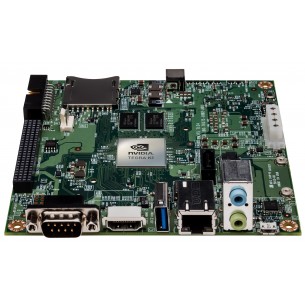
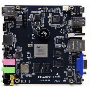
Quadia® Tegra® K1 SOC four-core computer supporting CUDA®, RoHS technology
No product available!
No product available!
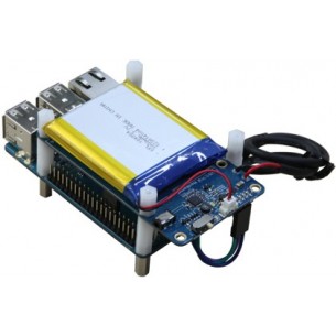
Odroid UPS2 is a UPS designed to work with Odroid C1, C1 + and C2 computers. It is equipped with a lithium-polymer battery with a capacity of 3000 mAh
No product available!
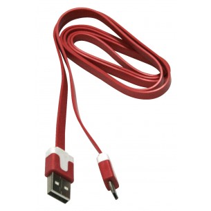
Flat USB cable A - micro-B USB with a length of 1 m, cable in red
No product available!
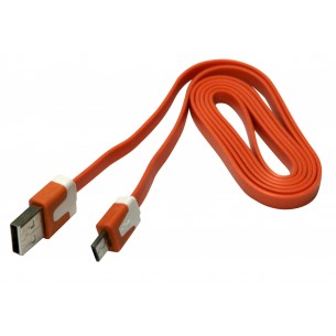
Flat USB cable A - micro-B USB with a length of 1 m, cable in orange
No product available!
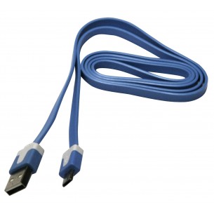
Flat USB cable A - micro-B USB with a length of 1m, cable in blue
No product available!
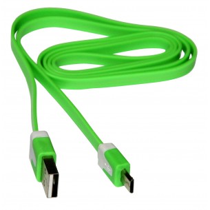
Flat USB cable A - micro-B USB with a length of 1m, cable in green
No product available!
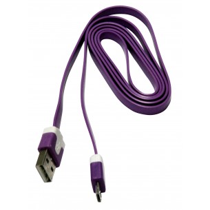
Flat USB cable A - micro-B USB with a length of 1 m, cable in purple
No product available!
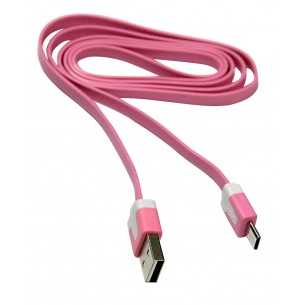
Flat USB cable A - micro-B USB with a length of 1 m, cable in a dark pink color
No product available!
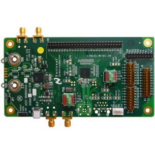
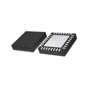
Kinetis L Series Cortex-M0+, 32bit MCU, 256 KB Flash , QFN32, Freescale, RoHS
No product available!
No product available!
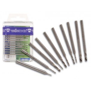
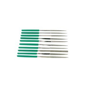
A set of 10 drill bits for precision work with diameters 0.6mm-2.3mm, RoHS
No product available!
No product available!
No product available!
No product available!