


zł21.87 tax excl.
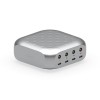
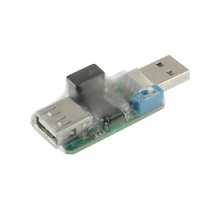
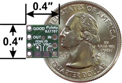
This RC switch converts hobby radio control pulses to digital on/off signals for use in RC switch and simple RC adapter applications. One output indicates the presence of a valid RC signal, and the other indicates whether the switch is active. The activation threshold and direction are configurable, and a safe-start feature reduces the likelihood of unexpected activation. Pololu 2801
The Pololu RC switch with Digital Output can be used with standard hobby radio control systems for radio control switch applications or simple interface applications. For example, this module can be used to convert unused RC receiver or servo controller channels to simple high/low signals that can control LEDs, MOSFETs, or relays, or it can serve as a simple interface between RC systems and microcontrollers that do not have the necessary resources for decoding hobby RC servo pulses. Two digital outputs indicate the presence of a valid signal and whether the switch is on or off.
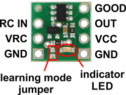
The board requires a 2.5–5.5 V power source supplied to VCC. The board can be powered by whatever digital system is reading the output, or it can be powered from the RC receiver if you bridge the surface-mount jumper on the bottom of the board that connects VRC to VCC.
The RC switch measures the width of incoming RC pulses and compares it to a user-configurable threshold (with ±64 µs of hysteresis) to decide whether to turn the output. By default, the threshold is approximately 1700 μs, with switch activation occurring above the threshold (longer pulses), but the switch has a learning mode that allows you to change the threshold and the activation direction. A safe-start feature reduces the likelihood of unexpected activation.
The RC switch provides feedback about what state it is in via a yellow indicator LED. Status information is also provided on two output pins:
Each of the these outputs can source or sink up to 25 mA.
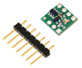
A 7-pin 0.1″ straight breakaway male header is included with the Pololu RC switch with Digital Output. The header pins can be used to connect the RC switch to perfboards or breadboards, or you can solder wires directly to the board for the most compact installation.
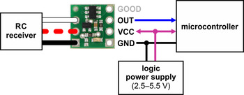
Typical wiring diagram for the Pololu RC Switch with Digital Output
Manufacturer BTC Korporacja sp. z o. o. Lwowska 5 05-120 Legionowo Poland sprzedaz@kamami.pl 22 767 36 20
Responsible person BTC Korporacja sp. z o. o. Lwowska 5 05-120 Legionowo Poland sprzedaz@kamami.pl 22 767 36 20
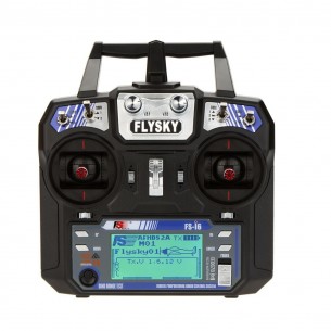
6-channel transmitter (RC apparatus) 2.4 GHz Flysky FS-i6 with LCD display in set with receiver FS-IA6 with telemetry support. 6V power supply (4 x AA battery). Left-hand throttle (right-handed version). Flysky FS-i6
No product available!
6-channel transmitter (RC apparatus) 2.4 GHz Flysky FS-i6 with LCD display included with FS-IA6 receiver with telemetry support. Power supply 6 V (4 x AA batteries), throttle on the right (left-handed version). Flysky FS-i6 Mode 1
No product available!
This RC switch converts hobby radio control pulses to digital on/off signals for use in RC switch and simple RC adapter applications. One output indicates the presence of a valid RC signal, and the other indicates whether the switch is active. The activation threshold and direction are configurable, and a safe-start feature reduces the likelihood of unexpected activation. Pololu 2801