


- Out-of-Stock


Dariusz Kościelnik
| Author: Dariusz Kościelnik ISBN: 83-206-1599-2 Format: B5, 372 pages Hardcover Publisher: WKiŁ |
| About the book |
| Manual on digital technology, devoted to the construction and programming of Nitron microcontrollers, being one of the newest and at the same time the smallest 8-bit systems from Motorola (and now Freescale Semiconductor). Both the CPU08 CPU itself and individual peripheral systems of Nitron microcontrollers are described in an accessible way. Particular attention was paid to the explanation of cause-and-effect relations between the configuration of particular modules and the exemplary situations that may occur during the operation of the system. The issues discussed are illustrated by examples of many practical devices. The presented programs or their fragments may help the reader to solve many problems encountered during the preparation of their own structures. Recipients: students of technical universities specializing in: IT, electronics and telecommunications, as well as hobbyists and engineers looking for modern electronic components for projects they carry out. Table of Contents INTRODUCTION 8 1. MICROCONTROLLER - SINGLE-MICROCOMPUTER 15 1.1. Microcontroller architecture 16 1.2. Program preparation for the microcontroller 25 1.3. The program execution process 32 1.4. Jump and branch commands 36 1.5. Calling subroutines and stack 41 1.6. Breaks 47 2. GENERAL CHARACTERISTICS OF NITRON 54 SERIES MICRO CONTROLLER 3. CENTRAL UNIT - CPUO8 63 3.1. The structure of the central unit 64 3.2. Central unit registers 66 3.2.1. Battery - A 67 3.2.2. Index register - H: X 67 3.2.3. Stack indicator - SP 68 3.2.4. Program counter - PC 70 3.2.5. State register - CCR 71 3.3. Addressing modes 74 3.3.1. Internal addressing 74 3.3.2. Immediate addressing 75 3.3.3. Direct addressing 76 3.3.4. Relative addressing 80 3.3.5. Index addressing 81 3.3.6. Addressing with the stack pointer 88 3.3.7. Address memory-memory 94 3.4. List of orders CPU08 99 3.4.1. Transmission orders 100 3.4.2. Arithmetic orders 104 3.4.3. Logical instructions 107 3.4.4. Bit forwarding instructions 108 3.4.5. Completion and test instructions 110 3.4.6. Orders operating on bits 113 3.4.7. Jump orders 114 3.4.8. Control commands 118 3.5. Central unit clock 123 3.6. CPU08 response to zeroing and interrupt signals 128 3.6.1. Reset signal 128 3.6.2. Break signal 129 3.7. Memory map of Nitron 136 series microcontrollers 4. PORTS AND PERIPHERALS 144 4.1. Ports of parallel transmission 146 4.1.1. PTA port 146 4.1.2. Port of PTB 153 4.1.3. Rules for programming PTA and PTB port lines 155 4.1.4. Example - communication with LCD display 162 4.2. Emulation of the serial transmission port 168 4.2.1. Example - digital thermometer with I2C 175 bus 4.3. External interrupt module - IRQ 186 4.3.1. The rules of correct operation of the external interrupt module 190 4.3.2. Example - digital clock 192 4.4. Keyboard module - KBI 201 4.4.1. Programming and operation of the 204 keyboard module 4.4.2. Example - combination lock with matrix keyboard 210 4.5. Analog-to-digital converter - ADC 218 4.5.1. Rules for the correct use of the ADC 227 module 4.5.2. Example - a voltmeter with an analogue ruler 229 4.6. Timer - TIM 234 4.6.1. Time base block 235 4.6.2. Channels of the TIM 246 module 4.6.3. Event logging mode - IC 247 4.6.4. Time comparator mode - OC 250 4.6.5. PWM signal generator mode 254 4.6.6. Cached mode 260 4.6.7. Rules for correct configuration and maintenance of the TIM 264 module 4.6.8. Example - fan speed control 268 5. CONFIGURATION AND OPERATING MODES MICRO CONTROLLER 272 5.1. Set of configuration registers - CONFIG 274 5.2. Time base generator module - OSC 277 5.2.1. Internal oscillator 281 5.2.2. RC 283 Resonant Circuit 5.2.3. Quartz or ceramic resonator 284 5.2.4. External square wave generator 285 5.3. Microcontroller zeroing system - Reset 286 5.3.1. Resetting after switching on the supply voltage - POR 288 5.3.2. External reset signal - RST 290 5.3.3. Counter-supervisor system - COP 293 5.3.4. Zeroing as a result of downloading the wrong instruction code - ILOP 298 5.3.5. An attempt to download a command from an unlawful place - ILAD 299 5.3.6. System detecting low voltage level - LVI 301 5.4. Low power modes 307 5.4.1. Standby mode - Wait 311 5.4.2. Stop-stop mode 312 5.4.3. Automatic wake-up system - AWU 314 5.5. Introducing the microcontroller into monitor mode - MON08 317 5.5.1. Starting monitor mode in programmed state 321 5.5.2. Starting the monitor mode in a non-programmed state 327 D. APPENDIX 331 D. 1. Memory map of Nitron 333 series microcontrollers D.2. List of microcontroller registers 333 D.2.1. Registers of the central unit 333 D.2.2. Registers of peripheral systems 334 D.2.3. Configuration registers 338 D.2.4. Registers stored in Flash memory 339 D.3. Vector array of microcontrollers series Nitron 40 D.4. List of CPU 08 command instructions. 341 D.5. List of addressing modes 353 D.6. List of microcontroller housings of the Nitron 357 series D.7. Library of LCD display operating procedures - LCD_HC08 357 D. 7 .1. LCD_HT08.inc file 359 D.8. Library of procedures emulating the I2C port - I2C_HC08 361 D.8.1. File I2C_HC08.inc 363 D.9. Schematics used in examples 366 D.9.1. Devices with 7-segment display 367 D.9.2. Devices with LCD 367 display D.9.3. Devices with RS 232 369 interface D.9.4. Devices with matrix keyboard 369 LITERATURE 371 |
Braided tape designed to remove excess molten solder. 1.9 mm wide, 15 m long. CHEMTRONICS HQ-WICK-L5
No product available!
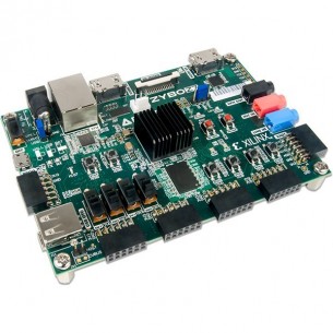
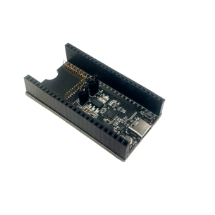
The ZYBO Z7 board (Zynq Board) is a renewed version of the set containing the programmable system from the Xilinx Zynq-7000 - Z-7020 family. Also includes the Xilinx Zynq SDSoC Voucher. Academic version. Digilent 471-015
No product available!
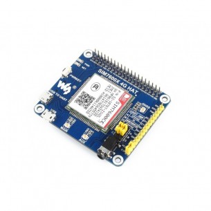
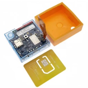
SIM7600CE 4G HAT is a module that extends the capabilities of Raspberry Pi for communication via GSM / GPRS cellular networks based on Simcom's SIM7600CE system. It has support for 4G / 3G / 2G / GSM / GPRS / GNSS. Waveshare SIM7600CE 4G HAT
No product available!
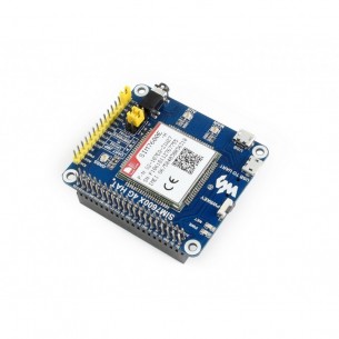
SIM7600E-H 4G HAT is an expansion module for Raspberry Pi for communication via GSM / GPRS cellular networks based on Simcom SIM7600E-H chipset. Waveshare SIM7600E 4G HAT
No product available!
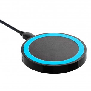
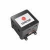
The Akyga induction charger allows you to charge your smartphone wirelessly using induction. QI technology ensures its compatibility with the majority of popular smartphones available on the market. 5 V output voltage, current efficiency is 1A. Akyga AK-QI-01
No product available!
Universal Akyga USB car charger powered from the cigarette lighter socket. Supply voltage 12 / 24V, output voltage 5V / 1A. Akyga AK-CH-01
No product available!
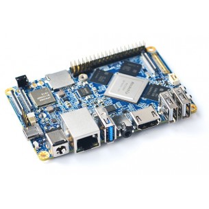
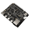
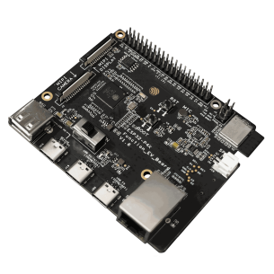
Minicomputer with a dual-core processor (up to 2.0 GHz) and 4 GB of LPDDR3 RAM memory, 16 GB of eMMC Flash memory. It has a two-band WiFi 2.4G and 5G module. Supports GPU and VPU acceleration. It has video interfaces in the form of HDMI, as well as USB 3.0, USB2.0, MicroSD, Ethernet port and 3.5mm audio socket. FriendlyElec NanoPC-T4
No product available!
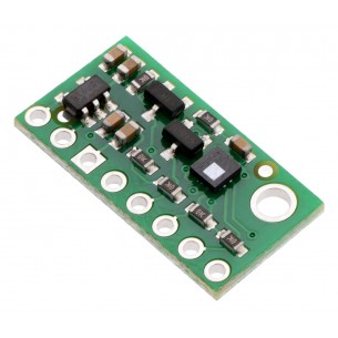
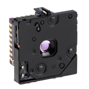
The module allows the measurement of atmospheric pressure in the range of 260 ... 1260hPa with a resolution of 0.02hPa. It has a built-in stabilizer and translator levels, so you can use it in systems supplied with voltage of 2.5 ... 5.5V. Pololu 2867
No product available!
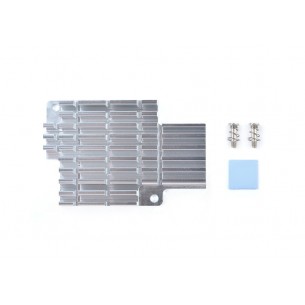
Kit with heatsink and assembly elements for the NanoPC T4 minicomputer. FriendlyELEC NanoPC T4 Heat SInk
No product available!
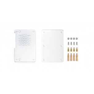
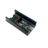
Acrylic glass case designed for NanoPC T3 Plus and NanoPC T4 minicomputers. FriendlyELEC T4 & T3 PLUS Acrylic Case
No product available!
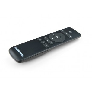
A universal IR remote designed for NanoPi M1, powered by two AAA batteries. FriendlyELEC RC-100
No product available!
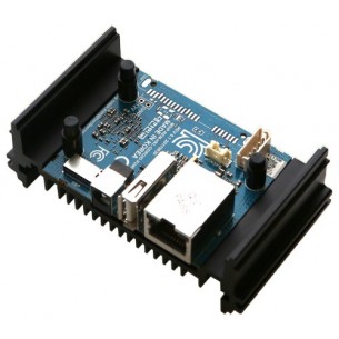
Odroid-MC1 Solo is a minicomputer with an Samsung Exynos5422 processor (ARM® Cortex ™ -A15 Quad 2.0GHz / Cortex ™ -A7 Quad 1.4GHz) which has 2 GB of RAM (LPDDR3) available. The module is dedicated to the construction of computer clusters, has a housing that allows you to connect multiple modules with each other.
No product available!
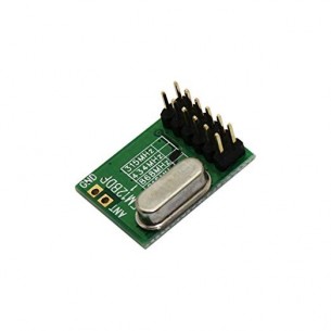
The ISM radio module in the DIP housing. It operates on the 868 MHz frequency. The module complies with FCC, ETSI regulations. HOPE MICROELECTRONICS RFM12B-868DP
No product available!
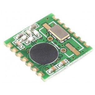
The ISM radio module in the SMD housing. It operates on the 868 MHz frequency. The module complies with FCC, ETSI regulations. HOPE MICROELECTRONICS RFM12B-868S2P
No product available!
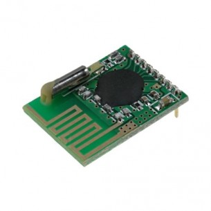
A GFSK transceiver operating in the ISM 2400 ... 2483.5 MHz frequency range. Powered by a voltage of 1.9 ... 3.6 V, the pins are goldpin connectors. It has a built-in PCB antenna. HOPE MICROELECTRONICS RFM73-D
No product available!
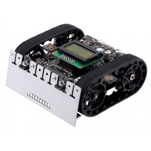
A minisumo robot on a tracked chassis with Pololu 75:1 HP motors. Fully assembled robot, additionally requires four AA batteries. Pololu 3126
No product available!
Dariusz Kościelnik