


- Out-of-Stock


The Arduino UNO WiFi board is based on the ATmega328 and it has an integrated ESP8266 WiFi Module. If you are starting out with Arduino, or starting with IoT, this is the board to get. A000133
The Arduino Uno Wi-Fi is the new Arduino Uno with an integrated Wi-Fi module! The board is based on the ATmega328P (datasheet) with an ESP8266 Wi-Fi Module integrated (datasheet). It has 14 digital input/output pins (of which 6 can be used as PWM outputs), 6 analog inputs, a 16 MHz ceramic resonator, a USB connection, a power jack, an ICSP header, and a reset button. It contains everything needed to support the microcontroller; simply connect it to a computer with a USB cable or power it with an AC-to-DC adapter or battery to get started.
The ESP8266 Wi-Fi Module is a self contained SoC with integrated TCP/IP protocol stack that can give access to your Wi-Fi network. (Or the device can act as an access point.) One useful feature of Uno Wi-Fi is support for OTA (over-the-air) programming, either for transfer of Arduino sketches or Wi-Fi firmware.
Power
Memory
Input and Output
Communication
The Arduino Uno Wi-Fi has a number of facilities for communicating with a computer, another Arduino, or other microcontrollers. The ATmega328 provides UART TTL (5V) serial communication, which is available on digital pins 0 (RX) and 1 (TX). An ATmega16U2 on the board channels this serial communication over USB and appears as a virtual com port to software on the computer. The 16U2 firmware uses the standard USB COM drivers, and no external driver is needed. However, on Windows, a .inf file is required. The Arduino software includes a serial monitor which allows simple textual data to be sent to and from the Arduino board. The RX and TX LEDs on the board will flash when data is being transmitted via the USB-to-serial chip and USB connection to the computer (but not for serial communication on pins 0 and 1).
A SoftwareSerial library allows for serial communication on any of the Uno's digital pins.
The ATmega328 also supports I2C (TWI) and SPI communication. The Arduino software includes a Wire library to simplify use of the I2C bus; For SPI communication, use the SPI library.
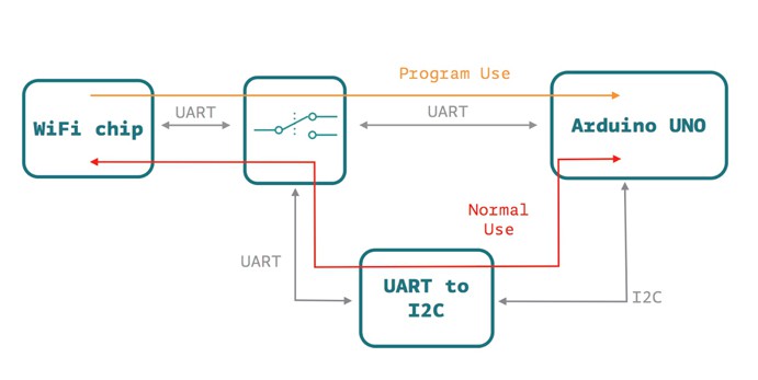
On the Arduino Uno Wi-Fi there’s a SC16IS750IBS IO Expander Single UART with I2C-bus/SPI interface that allows the communication between AtMega 16u2, AtMega 328p and the ESP8266EX.
The Arduino Uno Wi-Fi allow you to communicate via Wi-Fi with your sensors or actuators mounted on your board to create easily and quickly your IoT System. You can use your Arduino Uno Wi-Fi as a client of your Wi-Fi network, as a server to connect other client devices or you can create an ad’hoc Wi-Fi connection.
The perfect way to communicate to internet via your Arduino Uno Wi-Fi is the Ciao Library and using, for example, the REST connector.
On the Arduino Uno Wi-Fi is pre-uploaded the RestServer sketch that allows you to command immediately your board via browser:
Connect to the Arduino Uno Wi-Fi SSID and go to the link http://192.168.240.1/arduino/digital/13/1 to turn ON the LED L
Here other possible commands:
Arduino Microcontroller Features
Microprocessor ESP8266
Manufacturer BTC Korporacja sp. z o. o. Lwowska 5 05-120 Legionowo Poland sprzedaz@kamami.pl 22 767 36 20
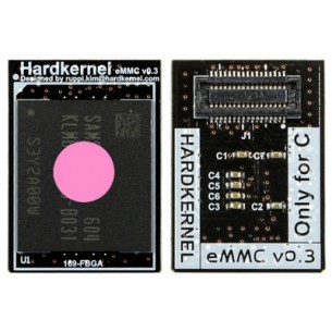
Pre-installed Ubuntu 14.04 or latest version. eMMC Version 5.0 interface or higher version from Samsung.
JEDEC/MMCA version 5.0 : HS400 interface with 8bit DDR mode
No product available!
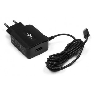
5V / 3.1A eXtreme power supply with microUSB plug for all Raspberry Pi computers (including Pi 3 model B and Pi 3 model B +)
No product available!
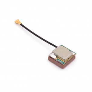
Antenna with built-in LNA amplifier with high sensitivity, for mounting in a device using a GPS module. The antenna has a 25mm cable, terminated with a U.FL plug (IPEX). Dimensions of the device: 9 x 9 x 4mm
No product available!
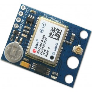
The GY-GPS6MV1 module is a board containing the U-blox NEO-6M GPS receiver system. The tile also includes RTC backup battery, antenna connector (U.FL), voltage stabilizer and UART signal outputs
No product available!
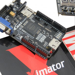
Kit: MAXimator, MAXimator Expander, ZL32PRG - USB Blaster PRO
No product available!
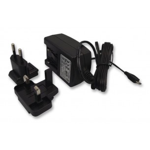
Power Supply 2.5A 5.1V for Raspberry Pi 3 model B - STONTRONICS T5875DV
No product available!
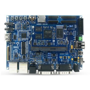
MYD-JA5D44 Development Board is a complete educational platform. Its heart is the MYIR MYC-JA5D44 module, which was equipped with the Atmel SAMA5D44 processor based on Cortex-A5 cores. The processor can work at a maximum frequency of 600 MHz. Min. RS232, RS485 connectors, HDMI connector, 3.5 mm Jack Audio inputs, microSD memory card slot, 10/100 Mbps Ethernet slot and many more.
No product available!
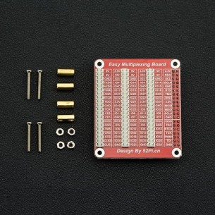
The Raspberry Pi GPIO Triple Expansion Board converts the single GPIO headers on your Raspberry Pi into three parts. DFR0385
No product available!
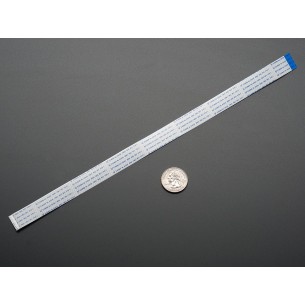
Flex Cable for Raspberry Pi Camera - 300mm / 12". Adafruit 1648
No product available!
Comes with a 6"x6" (152mm x 152mm) square of Pyralux. It\'s ED-Y type copper at 35um (1 oz/ft2) and has a polymide of 25um (1 mil). The thick copper layer means it can carry a lot of current, and its trivial to solder to it. Adafruit 1894
No product available!
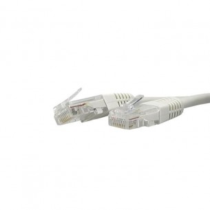
Patchcord UTP 5E Ethernet cable with a length of 50 cm - gray, with 2xRJ45 connectors
No product available!
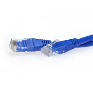
Patchcord UTP 5E Ethernet cable with a length of 50 cm - blue, with 2xRJ45 connectors
No product available!
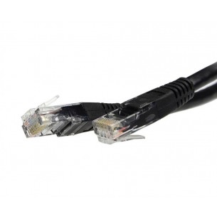
Patchcord UTP 5E Ethernet cable with a length of 1.5 m - black, with 2xRJ45 connectors
No product available!
Patchcord UTP 5E Ethernet cable with a length of 3 m - black, with 2xRJ45 connectors
No product available!
Patchcord UTP 5E Ethernet cable with a length of 5 m - blue, with 2xRJ45 connectors
No product available!
Patchcord UTP 5E Ethernet cable with a length of 5 m - gray, with 2xRJ45 connectors
No product available!
The Arduino UNO WiFi board is based on the ATmega328 and it has an integrated ESP8266 WiFi Module. If you are starting out with Arduino, or starting with IoT, this is the board to get. A000133