


- Out-of-Stock


The Arduino Robot is the first official Arduino on wheels. The robot chassis is comprised of two serially connected platforms, each of which features an ATmega32U4 and acts as an independent Arduino board. The upper platform, called the Control Board, includes a five-button keypad, knob potentiometer, color LCD, SD card reader (with SD card), speaker, and digital compass. The lower platform, or Motor Board, controls the two integrated DC motors and includes five reflectance sensors that can be used for line following or edge detection. The robot ships fully assembled and includes a USB cable, rechargable batteries, and a wall adapter for charging.
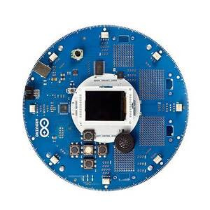 |
| Arduino Robot, top view. |
|---|
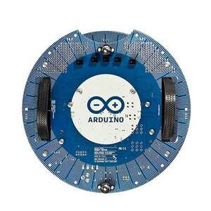 |
| Arduino Robot, bottom view. |
|---|
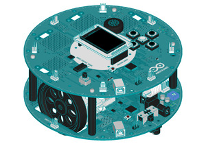 |
| Arduino Robot (rendered model). |
|---|
The Arduino robot is a great way to learn about electronics, mechanics, and embedded programming. It ships fully assembled and ready to program out of the box, and it includes a USB cable, four rechargeable AA batteries, a 9V wall adapter with US-style plug for charging, and an SD card preloaded with images and sound files used in the example Arduino Robot projects.
This Arduino-controlled robot platform consists of a Control Board stacked on top of a Motor Board, both of which are based on the ATmega32U4 (the same microcontroller used by the Arduino Leonardo) and function as independently programmed Arduino modules. The Control Board is generally used for reading sensors and making high-level decisions about how the robot should operate, while the Motor Board’s main purpose is to control the motors; a 10-pin connector carries serial communication, power, and additional information (like the battery’s current charge) from one board to the other so they can coordinate their actions.
The Arduino Robot has many integrated hardware peripherals for interacting with the user and the robot’s environment. The Control Board features a 5-button keypad, potentiometer, 160A—120-pixel color LCD, speaker, digital compass, SD card reader, a reset button, and 4 prototyping areas. It also has 5 digital I/O pins (of which 4 can be used as analog input pins), 6 PWM channels, and 8 possible analog input pins (multiplexed). The Motor Board has 5 reflectance sensors (with indicator LEDs) for line following or edge detection, 2 prototyping areas, 4 digital I/O pins (which can all be used as analog input pins), and a trimmer for motor calibration. A protective cover is included and can be attached to the bottom of the Motor Board to help prevent it from getting damaged.
Programming the robot is similar to programming the Arduino Leonardo: the robot’s two ATmega32U4 microcontrollers have built-in USB functionality, eliminating the need for a secondary processor dedicated to programming. The boards will appear to a connected computer as a virtual (CDC) serial / COM port. Each board has a separate USB product identifier and will show up as a different port on your Arduino IDE. It is important to choose the right one when programming. An Arduino library makes it easy to interface with the included hardware peripherals, and there are a number of project examples to get you started. See Arduino’s getting started page for more detailed information.
The Arduino Robot can be powered via USB or with 4 rechargable NiMH AA batteries; the power source is selected automatically. (For safety purposes, the motors are disabled when the robot is powered from USB.) The robot features an integrated battery charger that is active whenever the included 9 V AC-to-DC adapter is connected to the Motor Board’s power jack and USB is disconnected, so you must only use rechargeable batteries with the Arduino Robot.
More information about the Arduino Robot is available on Arduino’s website.
The characteristics of the Control Board and Motor Board are shown below.
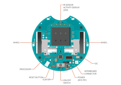 |
| Arduino Robot hardware diagram, top view of Motor Board. |
|---|
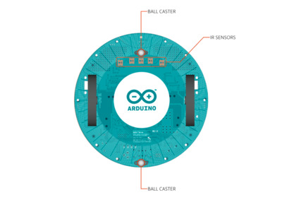 |
| Arduino Robot hardware diagram, bottom view of Motor Board. |
|---|
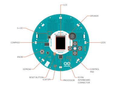 |
| Arduino Robot hardware diagram, top view of Control Board |
|---|
Motor Board
Control Board
Manufacturer BTC Korporacja sp. z o. o. Lwowska 5 05-120 Legionowo Poland sprzedaz@kamami.pl 22 767 36 20
Responsible person BTC Korporacja sp. z o. o. Lwowska 5 05-120 Legionowo Poland sprzedaz@kamami.pl 22 767 36 20
No product available!
No product available!
No product available!
No product available!
No product available!
No product available!
No product available!
No product available!
No product available!
No product available!
No product available!
No product available!
No product available!
No product available!
No product available!
AUTOMOBILE ALARM CONTROL PANEL WITH VARIAGE PASSWORD AND RS485 - PLATEBOARD AND PROGRAMMED LAYOUT
No product available!