


- Out-of-Stock


| Author: Artur Król, Joanna Moczko-Król ISBN: 83-86969-54-7 Format: B5, 400 pages Soft binding Publisher: Nakom |
| About the book |
| Book with a CD-ROM. The book contains a description of the S5 / S7 Windows program for programming PLC controllers. It presents, among others, functions of the S5 family controllers and the capabilities of the controller working in real time. The CD-ROM includes demo versions of the Windows and WinCC S5 / S7 programs with numerous examples. Table of Contents: Introduction Chapter 1. Installing programs for SIEMENS controllers 1.1. Windows S5 / S7 installation 1.2. WinCC installation Chapter 2. First steps - a simple lighting control system 2. l. Starting the program 2.2. Declaration of symbols table 2.3. Creating a control program 2.4. Simulation of the program 2.5. Testing the program using Real Time SPS 2.6. Process visualization using WinCC Chapter 3. Windows S5 / S7 program 3.1. Graphic command strips 3.2. Menu commands Dalei (File) 3.3. Baustein (Block) menu commands 3.4. Menu commands Sonstiges (Options) 3.5. Fenster menu commands (Window) 3.5. 1. Bindings - Querverweis (Cross Reference) 3.5.2. Controller status - Bausteinstatus (Block Status) 3.5.3. Symbol table editor - Symboltabelle (Symbolic Table) 3.5.4. List of blocks contained in the controller - SPS Bausteinverzeichnis (PLC Block List) 3.5.5. Status of inputs, outputs of the external controller - SPS Eingange, Ausgange usw. Zustand Externe SPS (PLC Inputs, Outputs, etc ...) 3.5.6. Diagnosis of errors - SPS Unterbrechungsstack (PLC Interrupt Stack) 3.5.7. Simulator of the program - S5-Simulations-SPS (S5 Simulation PLC) 3.6. Hilfe menu commands (Help) Chapter 4. Ways of project presentation in S5 / S7 Windows 4. l. The manner of presentation of block segments in the form of a list of instructions - AWL (STL) 4.1. Baustein (Block) menu commands 4. .2. The Bearbeiten menu commands (Modify) 4. .3. Suchen menu commands (Search) 4. .4. Menu commands Einfűgen (Insert) 4. .5. Darstellung menu commands (Presentation) 4. .6. Sample project in the form of a list of instructions 4.2. Presentation of the project in the form of logical functors - FUP (CSF) 4.2.1. Graphic tool bar 4.2.2. Baustein (Block) menu commands 4.2.3. The Bearbeiten menu commands (Modify) 4.2.4. Suchen menu commands (Search) 4.2.5. Menu commands Einfiigen (Insert) 4.2.6. Darstellung menu commands (Presentation) 4.2.7. Example project in the form of logical functors 4.3. Presentation of the project in the form of a contact diagram - KOP (LAD) 4.3.1. Graphic tool bar 4.3.2. Baustein (Block) menu commands 4.3.3. The Bearbeiten menu commands (Modify) 4.3.4. Suchen menu commands (Search) 4.3.5. Menu commands Einfiigen (Insert) 4.3.6. Darstellung menu commands (Presentation) 4.3.7. An example project in the form of a contact diagram Chapter 5. GS GS Windows editor 5.1. Graphic tool list 5.2. Baustein (Block) menu commands 5.3. The Bearbeiten menu commands (Modify) 5.4. Menu commands Einfiigen (Insert) 5.5. An example project in the Windows G5 language Chapter 6. Real Time SPS - software driver S5 CPU945 Chapter 7. DDE connection - dynamic data exchange Chapter 8. Introduction to STEP 5 and program processing 8.1. Program structure 8.2. Ways of presentation 8.3. Types of registers (CPU945) 8.4. Types of arguments and parameterization of function blocks (CPU945) 8.5. Organization and cyclic processing of the program 8.6. Program processing controlled by interruptions and time controlled Chapter 9. Description of functions in STEP 5 9.1. Binary functions 9. .1. Combinational functions 9. .2. Memory functions 9. .3. Time functions 9. .4. Pulse counting functions 9. .5. Bit testing functions 9.2. Digital functions 9.2.1. Charging functions 9.2.2. Transfer functions 9.2.3. Comparison functions 9.2.4. Arithmetic functions 9.2.5. Digital connection features 9.2.6. Digital system functions 9.3. Organizational functions 9.3. l. Block handling functions 9.3.2. Jump functions 9.3.3. Shift functions 9.3.4. Transforming functions 9.3.5. Processing functions 9.4. Functions with formal arguments 9.4. l. Binary functions with a formal argument 9.4.2. Digital functions with a formal argument 9.5. Integrated special functions 9.5.1. Integrated function blocks 9.5.2. Integrated organizational blocks Chapter 10. Testing functions 10. l. Testing of elementary binary functions in connection with the memory function 10.2. Testing the time element 10.3. Counter testing 10.4. Using the landing function to test the comparison function 10.5. Arithmetic division on floating point numbers 10.6. A combination of conditional and unconditional jump 10.7. Testing the transforming function 10.8. Testing of processing functions 10.9. The way of defining functions with formal arguments 10.10. A code converter using an integrated function block Chapter 11. The use of fault diagnosis for the analysis of disturbances 11.1. Stop program processing caused by exceeding the cycle time 11.2. Analysis of errors committed in the user's program 11.3. Checking the correctness of the STATUS register bits setting Chapter 12. Sample programs 12. l. Control of the light system at the pedestrian crossing 12.1.1. System description 12.1.2. Identification of all variables appearing in the program 12.1.3. Declaration of symbols table 12.1.4. Creating the control program code 12.1.5. Simulation of the program 12.1.6. Testing the program using Real Time SPS 12.1.7. Comparison of blocks 12.1.8. Searching for variables in the program 12.1.9. Save and call the project 12.1.10. Visualization of the pedestrian crossing 12.2. Filling and emptying the tank 12.2.1. System description 12.2.2. Creating a control program 12.2.3. Visualization of the tank filling installation 12.3. Visualization of the railway crossing 12.3. l. Declaration of variables and process screen objects 12.3.2. Calling the program and testing the system 12.4. Implementation of the function y = xA2 12.4. l. Creating the program 12.4.2. Generation and reading of data in LabVIEW 12.4.3. Generation and data output in MATLAB 12.5. An example of Real Time SPS connection with an object in MATLAB 12.5.1. Setting the regulator's settings 12.5.2. Construction of a control program 12.5.3. The structure of the connection between the object and the controller 12.5.4. Simulation of the control system Appendix A. Overview of controller functions (CPU945) A l. Binary functions A2. Digital functions A3. Organizational functions A4. Functions with formal arguments A5. Integrated special functions Literature Index 15.10. Optimism in the Pareto sense and multi-criteria optimization Part III. Design and simulation of control systems |
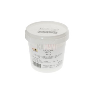
Technical vaseline is a universal lubricant with a wide range of applications, characterized by water resistance, resistance to oxidation and external factors, thermal stability and safety of use on rubber and most plastics
No product available!
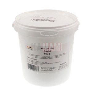
Technical vaseline is a universal lubricant with a wide range of applications, characterized by water resistance, resistance to oxidation and external factors, thermal stability and safety of use on rubber and most plastics
No product available!
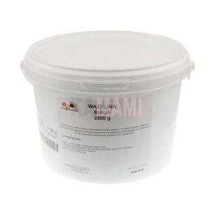
Technical vaseline is a universal lubricant with a wide range of applications, characterized by water resistance, resistance to oxidation and external factors, thermal stability and safety of use on rubber and most plastics
No product available!
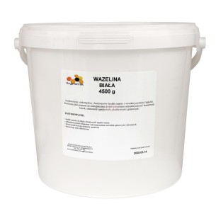
Technical vaseline is a universal lubricant with a wide range of applications, characterized by water resistance, resistance to oxidation and external factors, thermal stability and safety of use on rubber and most plastics
No product available!
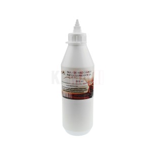
Shredder oil is a product that ensures optimal lubrication of shredder knives, extending its life, increasing work efficiency and preventing paper jams
No product available!
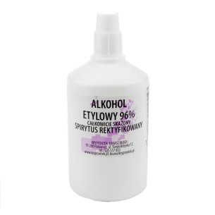
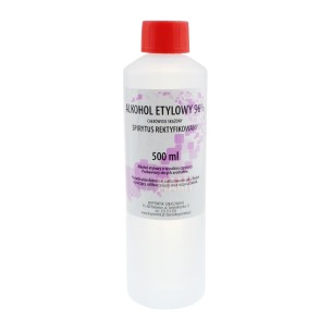
Ethyl alcohol is a universal solvent that perfectly cleans and degreases various types of surfaces, including delicate electronic components, constituting an essential element of workshop, electronic service or laboratory equipment
No product available!
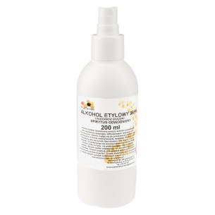
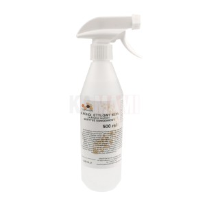
Ethyl alcohol is a universal solvent that perfectly cleans and degreases various types of surfaces, including delicate electronic components, constituting an essential element of workshop, electronic service or laboratory equipment
No product available!
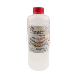
Ethyl alcohol is a universal solvent that perfectly cleans and degreases various types of surfaces, including delicate electronic components, constituting an essential element of workshop, electronic service or laboratory equipment
No product available!
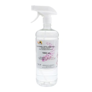
Ethyl alcohol is a universal solvent that perfectly cleans and degreases various types of surfaces, including delicate electronic components, constituting an essential element of workshop, electronic service or laboratory equipment
No product available!
Ethyl alcohol is a universal solvent that perfectly cleans and degreases various types of surfaces, including delicate electronic components, constituting an essential element of workshop, electronic service or laboratory equipment
No product available!
Ethyl alcohol is a universal solvent that perfectly cleans and degreases various types of surfaces, including delicate electronic components, constituting an essential element of workshop, electronic service or laboratory equipment
No product available!
Ethyl alcohol is a universal solvent that perfectly cleans and degreases various types of surfaces, including delicate electronic components, constituting an essential element of workshop, electronic service or laboratory equipment
No product available!
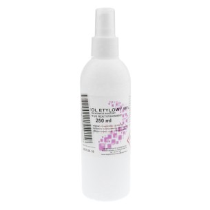
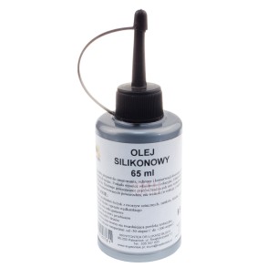
Silicone oil in a 65ml plastic bottle with oil jug is an essential tool offering excellent lubricating and protective properties, compatible with rubber and plastics, ideal for a wide range of workshop applications and maintenance of precision mechanisms
No product available!
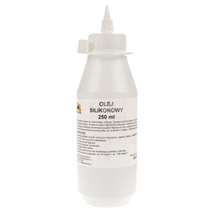
Silicone oil in a 250 ml plastic bottle with oil jug is an essential tool offering excellent lubricating and protective properties, compatible with rubber and plastics, ideal for a wide range of workshop applications and maintenance of precision mechanisms
No product available!
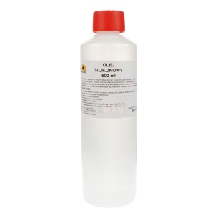
Silicone oil in a 500 ml plastic bottle is an essential tool offering excellent lubricating and protective properties, compatible with rubber and plastics, ideal for a wide range of workshop applications and maintenance of precision mechanisms
No product available!
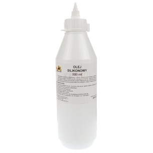
Silicone oil in a 500 ml plastic bottle with oil jug is an essential tool offering excellent lubricating and protective properties, compatible with rubber and plastics, ideal for a wide range of workshop applications and maintenance of precision mechanisms
No product available!