


- Out-of-Stock
")
")
")
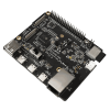
The Arduino M0 represents a simple, yet powerful, 32-bit extension of the Arduino UNO platform. The board is powered by Atmel’s SAMD21 MCU, featuring a 32-bit ARM Cortex® M0 core.
OVERVIEW
With the new Arduino M0 board, the more creative individual will have the potential to create one’s most imaginative and new ideas for IoT devices, wearable technologies, high tech automation, wild robotics and other not yet thinkable adventures in the world of makers.
The Arduino M0 represents a simple, yet powerful, 32-bit extension of the Arduino UNO platform. The board is powered by Atmel’s SAMD21 MCU, featuring a 32-bit ARM Cortex® M0 core.
With the addition of the M0 board, the Arduino family becomes larger with a new member providing increased performance.
The power of its Atmel’s core gives this board an upgraded flexibility and boosts the scope of projects one can think of and make; moreover, it makes the M0 the ideal educational tool for learning about 32-bit application development.
TECHNICAL DETAILS
Schematic & Reference Design
Power
The Arduino M0 can be powered via the micro USB connection or with an external power supply. The power source is selected automatically.
External (non-USB) power can come either from an AC-to-DC adapter (wall-wart) or battery. The adapter can be connected to the board by plugging a 2.1mm center-positive plug into the boards power jack. Leads from a battery can be inserted in the Gnd and Vin pin headers of the POWER connector.
| Power input | Voltage requirements | Current requirements | Connector marking |
|---|---|---|---|
| External power | 5V ± 2 % (± 100mV) for USB host operation. 4.3V to 5.5V if USB host operation is not required | Recommended minimum is 1A to be able to provide enough current for connected USB devices and the board itself. Recommended maximum is 2A due to the input protection maximum current specification. | PWR |
| Target USB | 4.4V to 5.25V (according to USB spec) | 500mA (according to USB spec) | TARGET USB |
The kit will automatically detect which power sources are available and choose which one to use according to the following priority:
External power is required when the 500mA through the USB connector is not enough to power a connected USB device in a USB host application.
The power pins are as follows:
Memory
The ATSAMD21G18 has 256 KB (with 4 KB used for the bootloader). The bootloader is factory pre burnt by Atmel and is stored in a dedicated ROM memory. The bootloader is protected using the NVM fuse.
It also carries 32 KB of SRAM and up to 16KB by emulation of EEPROM (which can be read and written with the EEPROM library).
Input and Output
Each of the 20 digital i/o pins on the M0 can be used as an input or output, using pinMode(), digitalWrite(), and digitalRead() functions. They operate at 3.3 volts. 7mA as maximum DC current for I/O pins and an internal pull-up resistor (disconnected by default) of 20-50 kOhms. In addition, some pins have specialized functions:
There are a couple of other pins on the board:
Communication
The Arduino M0 has a number of facilities for communicating with a computer, with another Arduino or other microcontrollers, and with different devices like phones, tablets, cameras and so on. The SAMD21 provides one hardware UART and three hardware USARTs for TTL (3.3V) serial communication.
The Arduino software includes a serial monitor allowing simple textual data to be sent to and from the board. The RX and TX LEDs on the board will flash when data is being transmitted via the ATSAMD21G18 chip and USB connection to the computer (but not for serial communication on pins 0 and 1).
The Native USB port is connected to the SAMD21. It allows for serial (CDC) communication over USB. This provides a serial connection to the Serial Monitor or other applications on your computer. It also enables the Due to emulate a USB mouse or keyboard to an attached computer.
The Native USB port can also act as a USB host for connected peripherals such as mice, keyboards, and smartphones.
The SAMD21 also supports TWI and SPI communication. The Arduino software includes a Wire library to simplify use of the TWI bus. For SPI communication, use the SPI library.
Programming
The Arduino M0 can be programmed with the Arduino software (download).
If you use Linux-based OS follow the guide Arduino IDE on Linux-based OS.
Uploading sketches to the SAMD21 is different from how it works with the AVR microcontrollers found in other Arduino boards: the flash memory needs to be erased before being re-programmed. Upload to the chip is managed by ROM on the SAMD21, which is run only when the chips flash memory is empty.
Both the USB ports can be used to program the board, though use of the Programming port is recommended, due to the way the erasing of the chip is handled:
USB Overcurrent Protection
The M0 has a resettable polyfuse that protects your computers USB ports from shorts and overcurrent. Although most computers provide their own internal protection, the fuse provides an extra layer of protection. If more than 500 mA is applied to the USB port, the fuse will automatically break the connection until the short or overload is removed.
Physical Characteristics
The maximum length and width of the M0 PCB are 2.7 and 2.1 inches respectively, with the USB connector and power jack extending beyond the former dimension. Four screw holes allow the board to be attached to a surface or case. Note that the distance between digital pins 7 and 8 is 160 mil (0.16"), not an even multiple of the 100 mil spacing of the other pins.
Conformity Declaration
Code: A000103
Data sheet
Manufacturer BTC Korporacja sp. z o. o. Lwowska 5 05-120 Legionowo Poland sprzedaz@kamami.pl 22 767 36 20
AUDIO PROCESSOR WITH EQ AND WIDMA ANALYZER - CONTINUOUS PLATE AND PROGRAMMED SYSTEM
No product available!
No product available!
No product available!
No product available!
No product available!
No product available!
No product available!
No product available!
No product available!
No product available!
No product available!
No product available!
No product available!
No product available!
No product available!
No product available!
The Arduino M0 represents a simple, yet powerful, 32-bit extension of the Arduino UNO platform. The board is powered by Atmel’s SAMD21 MCU, featuring a 32-bit ARM Cortex® M0 core.