


zł102.07 tax excl.
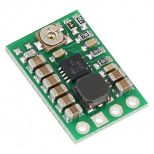
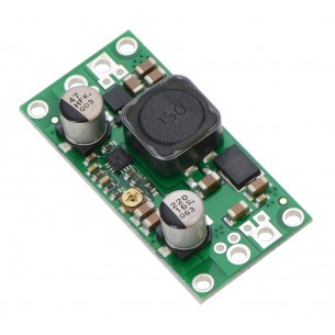
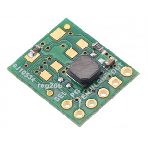
Pololu 5V Step-Up/Step-Down Voltage Regulator S18V20F5
Pololu 5V Step-Up/Step-Down Voltage Regulator S18V20F5
This powerful step-up/step-down regulator efficiently produces a fixed 5 V output from input voltages between 3 V and 30 V while allowing a typical output current of up to 2 A when the input voltage is close to the output voltage and offering typical efficiencies of 80% to 90%. Its ability to convert both higher and lower input voltages makes it useful for applications where the power supply voltage can vary greatly, as with batteries that start above but discharge below the regulated voltage.
Overview
These step-up/step-down regulators take an input voltage from 3 V to 30 V and increase or decrease it as necessary to produce a fixed 5 V, 6 V, 9 V, or 12 V output, depending on the version. They are switching regulators (also called switched-mode power supplies (SMPS) or DC-to-DC converters) with a single-ended primary-inductor converter (SEPIC) topology, and they have a typical efficiency between 80% and 90%. The available output current is a function of the input voltage, output voltage, and efficiency (see the Typical Efficiency and Output Current section below), but it will be around 2 A when the input voltage is close to the output voltage.
The S18V20x regulator family consists of the four fixed-output versions mentioned above along with two adjustable-output versions: the S18V20ALV offers an output range of 4 V to 12 V and the S18V20AHV offers an output range of 9 V to 30 V. The different versions of the board all look very similar, so the bottom silkscreen includes a blank space where you can add your own distinguishing marks or labels. This product page applies to all four fixed-output versions of the S18V20x family.
The flexibility in input voltage offered by these regulators is especially well-suited for battery-powered applications in which the battery voltage begins above the desired output voltage and drops below the target as the battery discharges. Without the typical restriction on the battery voltage staying above the required voltage throughout its life, new battery packs and form factors can be considered. For example:
The no-load quiescent will typically be between 1 mA and 5 mA for all possible combinations of input and output voltages (e.g. the quiescent current of the 12 V version is approximately 4 mA with 3 V in, 1.5 mA with 12 V in, and 1 mA with 30 V in). The ENABLE pin can be used to put the board in a low-power state that reduces the quiescent current to between 10 and 20 µA per volt on VIN (e.g. approximately 30 µA with 3 V in and 500 µA with 30 V in).
This regulator has built-in reverse-voltage protection, over-current protection, thermal shutdown (which typically activates at 165°C), and an under-voltage lockout that causes the regulator to turn off when the input voltage is below 2.5 V (typical).
For similarly powerful boost-only regulators, consider our U3V50x regulator family, which are typically more appropriate if you know that your input voltage will always be lower than your output voltage.
Features
1 32 V is the absolute maximum operating voltage; the recommended maximum operating voltage is 30 V, which is the limit of the reverse voltage protection.
Using the regulator
Connections
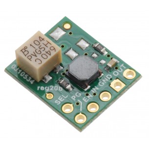
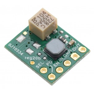
This step-up/step-down regulator has four connections: input voltage (VIN), ground (GND), and output voltage (VOUT), and ENABLE.
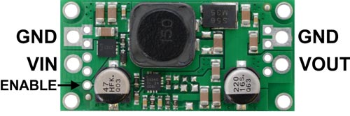
The input voltage, VIN, should be between 2.9 V and 32 V. Lower input voltages can cause the regulator to shut down or behave erratically; higher input voltages can destroy the regulator, so you should ensure that noise on the input is not excessive. 32 V should be treated as the absolute maximum input voltage. Our recommended maximum operating voltage is 30 V, which is the limit of the reverse voltage protection.
The regulator is enabled by default: a 100 kΩ pull-up resistor on the board connects the ENABLE pin to reverse-protected VIN. The ENABLE pin can be driven low (under 0.7 V) to put the board into a low-power state. The quiescent current draw in this sleep mode is dominated by the current in the pull-up resistor from ENABLE to VIN and by the reverse-voltage protection circuit, which will draw between 10 µA and 20 µA per volt on VIN when ENABLE is held low (e.g. approximately 30 µA with 3 V in and 500 µA with 30 V in). If you do not need this feature, you should leave the ENABLE pin disconnected. Note that the SEPIC topology has an inherent capacitor from input to output; therefore, the output is not completely disconnected from the input even when the regulator is shut down.
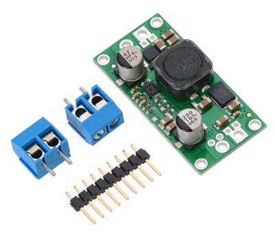
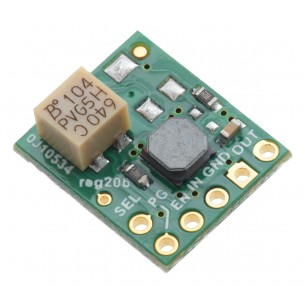
Pololu fixed step-up/step-down voltage regulator S18V20Fx with included optional terminal blocks and header pins.
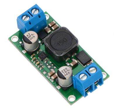
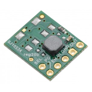
Pololu fixed step-up/step-down voltage regulator S18V20Fx, assembed with included terminal blocks.
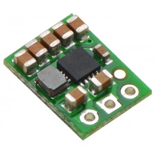
The connections are labeled on the back side of the PCB, and the board offers several options for making electrical connections. You can solder the included 2-pin 5mm-pitch terminal blocks to the two pairs of larger holes on the ends of the board. Alternatively, if you want to use this regulator with a solderless breadboard, 0.1″-pitch connectors, or other prototyping arrangements that use a 0.1″grid, you can solder pieces of the included 9×1 straight male header strip to the 0.1″-spaced smaller holes (each large through-hole has a corresponding pair of these smaller holes). For the most compact installation, you can solder wires directly to the board.
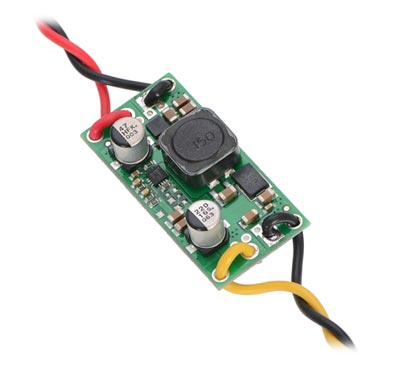
The board has four 0.086″ mounting holes intended for #2 or M2 screws. In applications where mounting screws are not used and wires are soldered directly to the board, the insulated part of the wires can be passed through the mounting holes for strain relief. The picture above shows an example of this with 20 AWG wire, which was close to the limit of what would fit through the mounting holes. Typical efficiency and output current.
The efficiency of a voltage regulator, defined as (Power out)/(Power in), is an important measure of its performance, especially when battery life or heat are concerns. As shown in the graphs below, these switching regulators have an efficiency of 80% to 90% for most combinations of input voltage, output voltage, and load.
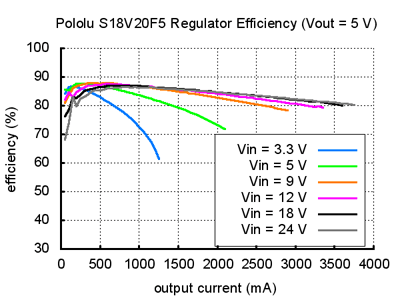
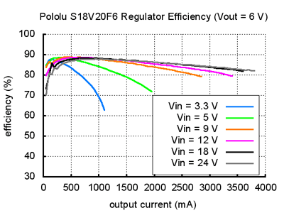
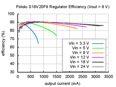
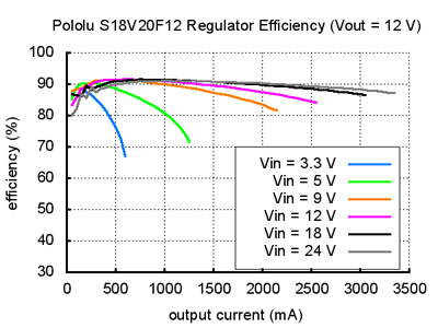
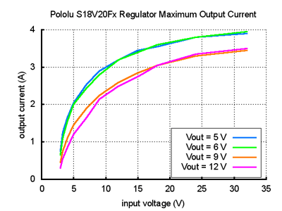
The maximum achievable output current of the board varies with the input voltage but also depends on other factors, including the ambient temperature, air flow, and heat sinking. The graphs below show output currents at which this voltage regulator’s over-temperature protection typically kicks in after a few seconds. These currents represent the limit of the regulator’s capability and cannot be sustained for long periods, so the continuous currents that the regulator can provide are typically several hundred milliamps lower.
Data sheet
Manufacturer BTC Korporacja sp. z o. o. Lwowska 5 05-120 Legionowo Poland sprzedaz@kamami.pl 22 767 36 20
Responsible person BTC Korporacja sp. z o. o. Lwowska 5 05-120 Legionowo Poland sprzedaz@kamami.pl 22 767 36 20
The Step-Up/Step-DownS7V8A Buck Voltage Regulator module with adjustable output voltage in range of 2.5-8V, input voltage range of 2.7-11.8V and a maximum output current of 0.5-1A. Pololu 2118
Pololu 5V Step-Up/Step-Down Voltage Regulator S7V7F5
The Step-Up/Step-DownS7V8F5 Buck Voltage Regulator module with output voltage 5V, input voltage range of 2.7-11.8V and a maximum output current of 0.5-1A. Pololu 2123
No product available!
The Step-Up / Step-Down S18V20F12 inverter module gives the output voltage of 12V with a wide input voltage range of 3 ... 30V and a maximum output current of 2A. Polol 2577
No product available!
This powerful step-up/step-down regulator efficiently produces an adjustable 4 V to 12 V output from input voltages between 3 V and 30 V while allowing a typical output current of up to 2 A when the input voltage is close to the output voltage and offering typical efficiencies of 80% to 90%.
No product available!
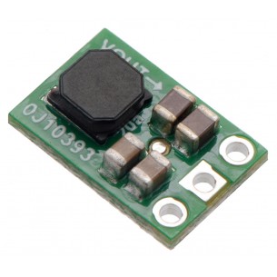
The S9V11F5 switching step-up/step-down regulator efficiently produces 5V from input voltages between 2V and 16V. Pololu 2836
No product available!
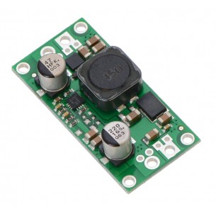
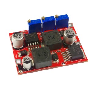
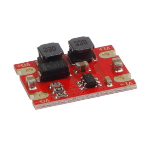
Module with LM2596 step-down converter and LM2577 step-up converter. The inverter has a battery and battery indicator with constant current
No product available!
The S9V11MACMA switching step-up/step-down regulator efficiently produces a finely adjustable output between 2.5 V and 9 V whether it is higher or lower than the input voltage, which can range from 3 V to 16 V. The regulator also has a precision-adjustable low-voltage cutoff with hysteresis that can be used to prevent battery over-discharge.
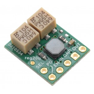
The S9V11F5S6CMA switching step-up/step-down regulator efficiently produces a fixed 5 V (default) or 6 V (selectable) output whether it is higher or lower than the input voltage, which can range from 2 V to 16 V. (Note: minimum start-up voltage is 3 V, but it operates to 2 V after that.)
The S9V11MA switching step-up/step-down regulator efficiently produces a finely adjustable output between 2.5 V and 9 V whether it is higher or lower than the input voltage, which can range from 2 V to 16 V. Pololu 2869
No product available!
The S9V11F3S5 switching step-up/step-down regulator efficiently produces a fixed 3.3 V (default) or 5 V (selectable) output whether it is higher or lower than the input voltage, which can range from 2 V to 16 V. (Note: minimum start-up voltage is 3 V, but it operates to 2 V after that.)
The S9V11F3S5CMA switching step-up/step-down regulator efficiently produces a fixed 3.3 V (default) or 5 V (selectable) output whether it is higher or lower than the input voltage, which can range from 2 V to 16 V. (Note: minimum start-up voltage is 3 V, but it operates to 2 V after that.)
No product available!
The S9V11F3S5C3 switching step-up/step-down regulator efficiently produces a fixed 3.3 V (default) or 5 V (selectable) output whether it is higher or lower than the input voltage, which can range from 3 V to 16 V. The regulator also has fixed 3.3 V low-voltage cutoff with hysteresis that can be used to prevent battery over-discharge.
Step-Up/Step-Down converter with an output voltage of 3.3 V, an input voltage of 2.5 to 15 V and a maximum current of 600 mA. DFRobot DFR0568
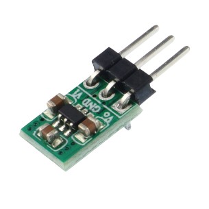
Step-Up/Step-Down converter with an output voltage of 3.3 V, an input voltage from 1.8 to 5 V and a maximum current of up to 100 mA
No product available!
Pololu 5V Step-Up/Step-Down Voltage Regulator S18V20F5