


zł70.49 tax excl.
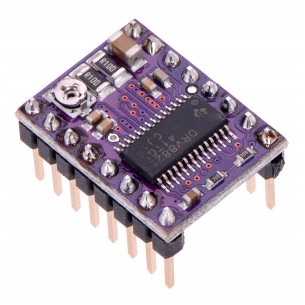
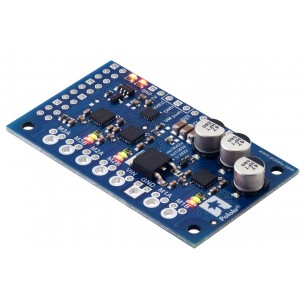
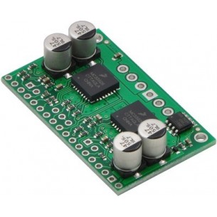
This is a breakout board for ON Semiconductor’s AMIS-30543 microstepping bipolar stepper motor driver, which features SPI-adjustable current limiting, 11 step modes (from full-step through 1/128-step), back-EMF feedback that can be used for stall detection or optional closed-loop control, and over-current and over-temperature protection.

free shipping in Poland for all orders over 500 PLN

If your payment will be credited to our account by 11:00

Each consumer can return the purchased goods within 14 days
This product is a carrier board or breakout board for ON Semiconductor’s AMIS-30543 Micro-Stepping Motor Driver. This stepper motor driver lets you control one bipolar stepper motor at up to 3 A output current per coil (see the Power Dissipation Considerations section below for more information). Here are some of the board’s key features:
Note: This driver needs to be enabled and configured through its SPI interface on power up, so your microcontroller must be capable of acting as an SPI master (either with an SPI peripheral or software SPI).
This product ships with all surface-mount components—including the AMIS-30543 driver IC—installed as shown in the product picture. However, soldering is required for assembly of the included through-hole parts. The following through-hole parts are included:
The 0.1″ male header can be broken or cut into smaller pieces as desired and soldered into the smaller through-holes. These headers are compatible with solderless breadboards, 0.1″ female connectors, and our premium and pre-crimped jumper wires. The terminal blocks can be soldered into the larger holes to allow for convenient temporary connections of unterminated power and stepper motor wires. You can also solder your motor leads and other connections directly to the board for the most compact installation.
| PIN | Description |
|---|---|
| VMOT | Reverse-protected 6 V to 30 V board power supply connection. Note: Available VDD current is reduced for input voltages under 8 V, and sleep mode is not available for input voltages under 9 V. |
| VBB | This pin gives access to the motor power supply after the reverse-voltage protection MOSFET (see the board schematic below). It can be used to supply reverse-protected power to other components in the system. It is generally intended as an output, but it can also be used to supply board power. |
| GND | Ground connection points for the motor power supply and control ground reference. The control source and the motor driver must share a common ground. |
| MOTXP | Motor output: “positive” end of phase X coil. |
| MOTXN | Motor output: “negative” end of phase X coil. |
| MOTYP | Motor output: “positive” end of phase Y coil. |
| MOTYN | Motor output: “negative” end of phase Y coil. |
| VDD (5V OUT) | The board is powered by an internal 5V regulator, and this pin gives access to the regulated 5 V output. This can be used to supply the neighboring IOREF pin when using this board in 5V systems, and it can be used to power an external microcontroller. When VMOT is over 8 V, approximately 30 mA is available for external components; when VMOT is less than 8 V, the available current drops to less than 10 mA. |
| IOREF | All of the board signal outputs (except SLA) are open-drain outputs that are pulled up to IOREF, so this pin should be supplied with the logic voltage of the controlling system (e.g. 3.3V for use in 3.3V systems). For convenience, it can be connected to the neighboring VDD pin when it is being used in a 5V system. |
| NXT | Changes on this input move the motor current one step up or down in the translator table (even when the motor is disabled). The edge that triggers the step depends on the NXT-polarity configuration bit, which can be changed through the SPI interface (rising edge by default). |
| DIR | Input that determines the direction of rotation. The direction can also be controlled through the SPI interface. |
| DO | SPI data output. (This pin is also often referred to as “MISO”.) |
| DI | SPI data input. (This pin is also often referred to as “MOSI”.) |
| CLK | SPI clock input. |
| CS | SPI chip select input. Logic transitions on this pin are required for SPI communication, even if this is the only device on the SPI bus. |
| CLR | Chip reset input. A logic high on this input clears all internal registers, except in sleep mode. |
| ERR | Error output. This pin drives low to indicate that an error condition has occurred. The specific error can be determined by using the SPI interface to check the error flags. |
| POR/WD | Power-on reset/watch dog function output. This pin provides an active-low signal that can be used as a reset input for an external microcontroller. |
| SLA (filtered) | SLA (speed and load angle) output after a low-pass filter. The result is an analog voltage between 0 V and 5 V that indicates the level of the back-EMF voltage of the motor. This signal can be used for stall detection or closed-loop control of the torque and speed based on the load angle. Note: Since the output of this pin ranges from 0 V to 5 V regardless of IOREF, extra precautions should be taken when connecting this pin to a 3.3V device (such as passing it through an appropriate voltage divider). |
If you are new to the AMIS-30543 or stepper motors in general, our AMIS-30543 Arduino library can help you get started. The library provides basic functions for configuring and operating the driver using an Arduinoor Arduino-compatible controller. It also provides access to many of the driver’s advanced features and includes example sketches that show you how to use them.
The AMIS-30543 driver IC has a maximum current rating of 3 A per coil, but the actual current you can deliver depends on how well you can keep the IC cool. The carrier’s printed circuit board is designed to draw heat out of the IC, but to supply more than approximately 1.8 A per coil continuously, a heat sink or other cooling method is required. However, it is possible to use the SPI-configurable current limit to selectively deliver higher currents than this for short durations without overheating the driver.
This product can get hot enough to burn you long before the chip overheats. Take care when handling this product and other components connected to it.
Please note that measuring the current draw at the power supply will generally not provide an accurate measure of the coil current. Since the input voltage to the driver can be significantly higher than the coil voltage, the measured current on the power supply can be quite a bit lower than the coil current (the driver and coil basically act like a switching step-down power supply). Also, if the supply voltage is very high compared to what the motor needs to achieve the set current, the duty cycle will be very low, which also leads to significant differences between average and RMS currents.
| Size: | 1.0″ × 1.2″ |
|---|---|
| Weight: | 4.0 g1 |
| Minimum operating voltage: | 6 V2 |
|---|---|
| Maximum operating voltage: | 30 V |
| Continuous current per phase: | 1.8 A3 |
| Maximum current per phase: | 3 A4 |
| Minimum logic voltage: | 2.5 V |
| Maximum logic voltage: | 5.5 V |
| Microstep resolutions: | full, 1/2, 1/4, 1/8, 1/16, 1/32, 1/64, 1/128 |
| Reverse voltage protection?: | Y |
Data sheet
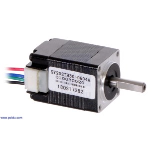
Bipolar stepper motor. It has a resolution of 200 steps/revolution (1.8° per step), a rated voltage of 3.9 V, and draws a current of 0.6 A per coil. Pololu 1204
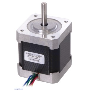
Bipolar stepper motor. It has a resolution of 200 steps/revolution (1.8° per step), has a nominal voltage of 4 V and draws a current of 1.2 A per coil. Pololu 1200
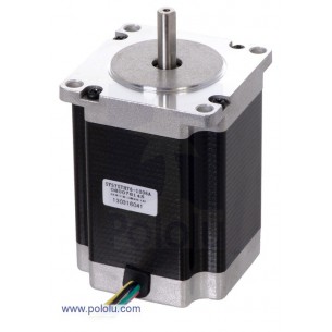
Unipolar/bipolar stepper motor. It has a resolution of 200 steps/revolution (1.8° per step), has a nominal voltage of 8.6 V, and draws a current of 1 A per coil. Pololu 1477
No product available!
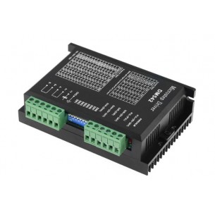
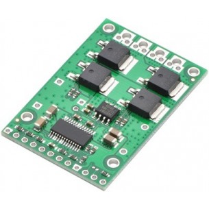
Stepper motor driver that can work with a voltage in the range from 20 to 50 V and a maximum current of 4.2 A. It allows you to configure the microstep in the range from 2 to 128. DM542
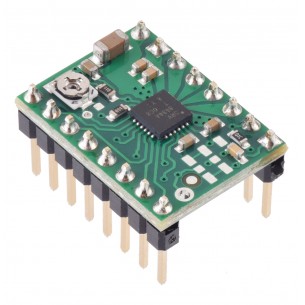
Module with a stepper motor driver based on the DRV8825 system. allows the bipolar motor to be supplied with current up to 1.5 A per phase, without the use of a heat sink. The system can be supplied with voltage up to 45 V. Pololu 2987
Extension board with stepper motor controller based on the STSPIN820 system. Ideally suited for use, among others in 2D / 3D printers, robots, cameras. Pololu 2878
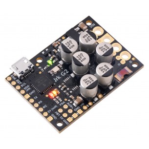
DC motor driver with voltage 6.5..30V and maximum continuous current 27A. It has the ability to easily implement the feedback loop and numerous control interfaces. Polol 3148
Pololu High-Power Motor Driver 24v23 CS
No product available!
The DC motor driver module enables the motor to be controlled using a PWM signal with several supply voltages (3V, 6V, 12V, 24V and 35V) and a maximum continuous current of 5A.
Two-channel DC motor driver with an operating voltage from 7 to 35 V and a maximum continuous current of 30 A. It can be controlled by an analog signal, PWM, UART, RC signal or by means of built-in buttons. Cytron MDDS30
Compact stepper motor controller with the TMC2208 system with operating voltage from 4 to 35 V. It offers smooth, quiet operation, high efficiency, various operating modes and easy configuration. It is controlled via the STEP/DIR interface and is an ideal solution for 3D printers and similar applications
Motor-driven expansion board for Arduino, L293D, 74HC595 shift register, RoHS
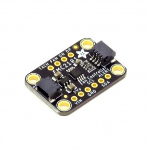
A module with a fan controller and a temperature sensor based on the EMC2101 system. Equipped with a STEMMA QT connector, it communicates via the I2C interface. Adafruit 4808
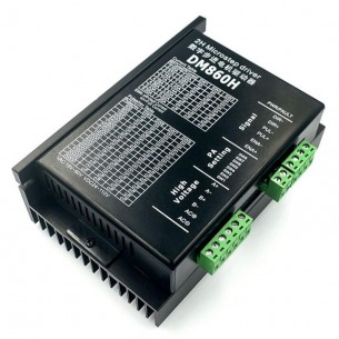
Stepper motor driver that can operate with a voltage in the range from 24 to 110 VDC or from 18 to 80 VAC and a maximum current of 7.2 A. It allows for microstep configuration in the range from 2 to 256. DM860H
DC motor driver that allows you to control the movement of two drives using the I2C interface. Board without connectors. Pololu 5056
No product available!
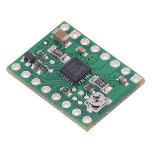
Module with a stepper motor driver based on the DRV8434A system. It allows the bipolar motor to be powered with a current of up to 1.2 A per phase and can be supplied with the voltage from 4.5 V to 45 V. Pololu 3765
No product available!
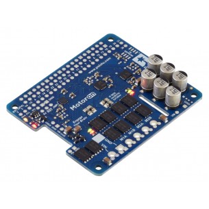
DC motor driver that allows you to control the movement of three drives using the I2C interface. Pololu 5035
A two-channel DC motor controller with a UART TTL interface. It is powered from 4.5 V to 48 V and can deliver up to 1.8 A per motor. Board with connectors for assembly. Pololu 5067
No product available!
Dual MC33926 Motor Driver CarrierTwo-channel DC motor controller with voltage from 5 V to 28 V, power consumption up to 3 A per channel. Controlled by PWM signal. Pololu 1213
No product available!
This is a breakout board for ON Semiconductor’s AMIS-30543 microstepping bipolar stepper motor driver, which features SPI-adjustable current limiting, 11 step modes (from full-step through 1/128-step), back-EMF feedback that can be used for stall detection or optional closed-loop control, and over-current and over-temperature protection.