


zł62.63 tax excl.
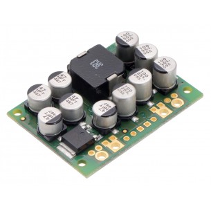
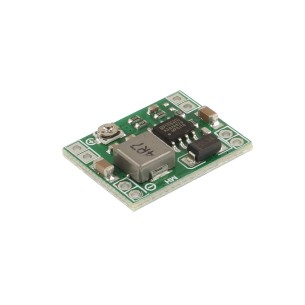
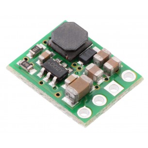
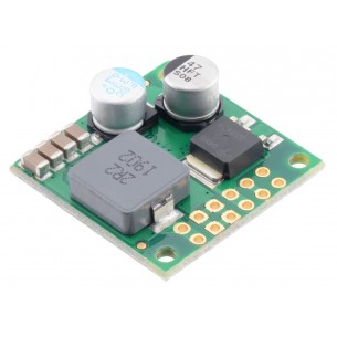
Step-Down Voltage Regulator D24V25F5. Pololu 2850

free shipping in Poland for all orders over 500 PLN

If your payment will be credited to our account by 11:00

Each consumer can return the purchased goods within 14 days
The D24V25Fx family of step-down voltage regulators generates lower output voltages from input voltages as high as 38 V. They are switching regulators (also called switched-mode power supplies (SMPS) or DC-to-DC converters) with typical efficiencies between 85% and 95%, which is much more efficient than linear voltage regulators, especially when the difference between the input and output voltage is large. The available output current is a function of the input voltage and efficiency (see the Typical efficiency and output current section below), but the output current can typically be as high as 2.5 A.
At light loads, the switching frequency automatically changes to maintain high efficiencies. These regulators have a typical quiescent (no load) current draw of less than 1 mA, and the ENABLE pin can be used to put the boards in a low-power state that reduces the quiescent current to approximately 10 µA to 20 µA per volt on VIN. The ENABLE pin can be used to reduce the quiescent current to a few hundred microamps.
The modules have built-in reverse-voltage protection, short-circuit protection, a thermal shutdown feature that helps prevent damage from overheating, and a soft-start feature that reduces inrush current.
Several different fixed output voltages are available.
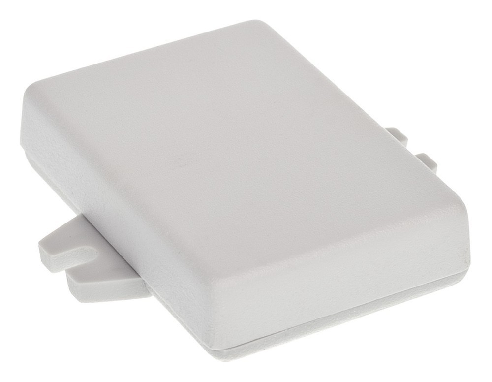
The input voltage, VIN, powers the regulator. Voltages between 4.5 V and 38 V can be applied to VIN, but for versions of the regulator that have an output voltage higher than 4.5 V, the effective lower limit of VIN is VOUT plus the regulator’s dropout voltage, which varies approximately linearly with the load (see below for graphs of dropout voltages as a function of the load).
The output voltage, VOUT, is fixed and depends on the regulator version: the D24V25F3 version outputs 3.3 V, the D24V25F5 version outputs 5 V, the D24V25F6 version outputs 6 V, the D24V25F7 version outputs 7.5 V, and the D24V5F9 version outputs 9 V.
The regulator is enabled by default: a 100 kΩ pull-up resistor on the board connects the ENABLE pin to reverse-protected VIN. The ENABLE pin can be driven low (under 0.6 V) to put the board into a low-power state. The quiescent current draw in this sleep mode is dominated by the current in the pull-up resistor from ENABLE to VIN and by the reverse-voltage protection circuit, which will draw between 10 µA and 20 µA per volt on VIN when ENABLE is held low. If you do not need this feature, you should leave the ENABLE pin disconnected.
The five connections are labeled on the top of the PCB and are arranged with a 0.1″ spacing for compatibility with solderless breadboards, connectors, and other prototyping arrangements that use a 0.1″ grid. Either the included 5×1 straight male header strip or the 5×1 right angle male header strip can be soldered into these holes. For the most compact installation, you can solder wires directly to the board.
Data sheet
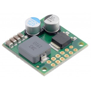
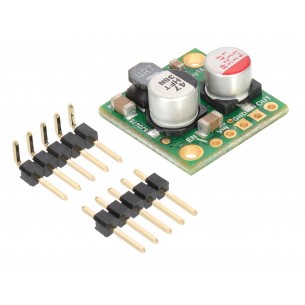
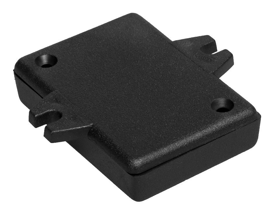
Step-Down DC-DC converter module based on the D24V150F9 chip. Input voltage 11 ... 40V, output voltage 9V (max 15A). Pololu 2884
This compact switching step-down voltage regulator. It has an output voltage range of 4 V to 25 V and a maximum output current of 600 mA. Pololu 3799
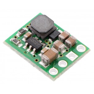
The very small step-down 6 V, 2.5 A synchronous inverter can be supplied with voltage up to 36 V, dimensions: 17.8 mm x 17.8 mm. Pololu 2859
No product available!
This compact (0.4″ × 0.5″) switching step-down (or buck) voltage regulator takes input voltages up to 50 V and efficiently reduces them to 9 V while allowing for a maximum output current of 600 mA. It has a very low dropout, so it can be used with input voltages that are within a few hundred millivolts of its output.
Step-Down converter D36V50F7 with an output voltage of 7.5 V, an input voltage from 8.3 to 50 V and a maximum output current of 7 A. Pololu 4093
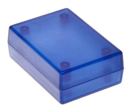
Przetwornica DC-DC Step Down (MP1584), Uwe 4.5..28V, Uwy regulowane 0.8..20V, RoHS
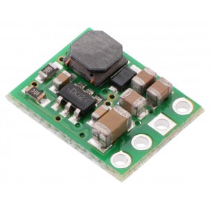
This small synchronous switching step-down (or buck) regulator takes an input voltage of up to 36V and efficiently reduces it to 5V. The board measures only 0.7″ × 0.7″ yet delivers a typical continuous output current of up to 2.5A and features reverse voltage protection. Pololu 2858
No product available!
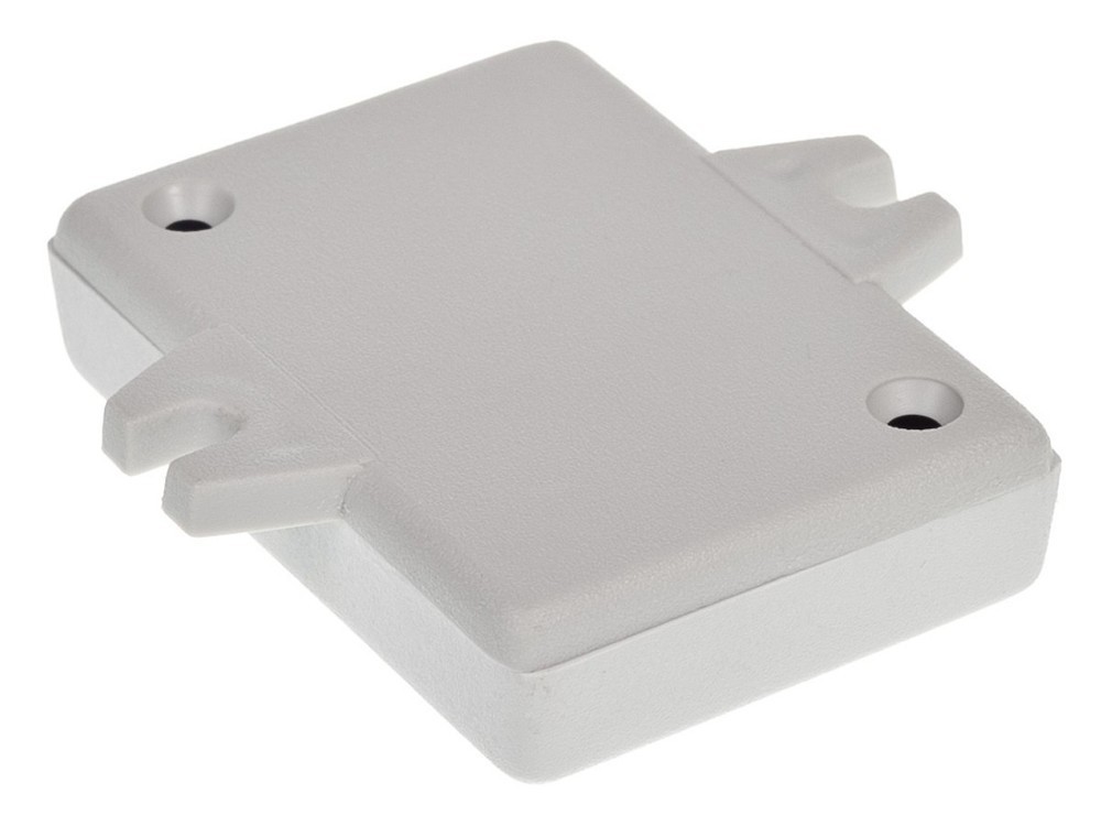
Step-Down converter D36V28F9 with an output voltage of 9 V, an input voltage from 9.8 to 50 V and a maximum output current of 3.4 A. Pololu 3785
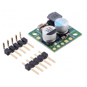
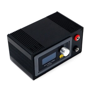
A power supply based on a DC-DC converter with a current capacity of up to 6.1 A. The input voltage can range from 6 V to 30 V, while the output voltage is adjustable from 0 V to 36 V. Enclosure version. XYL3606S
This compact (0.4″ × 0.5″) switching step-down (or buck) voltage regulator takes input voltages up to 50 V and efficiently reduces them to 15 V while allowing for a maximum output current of 600 mA. It has a very low dropout, so it can be used with input voltages that are within a few hundred millivolts of its output.
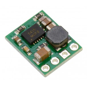
This small synchronous switching step-down (or buck) regulator takes an input voltage of up to 38 V and efficiently reduces it to 9 V. The board measures only 0.7″ × 0.7″, but it allows a typical continuous output current of up to 2.5 A. Typical efficiencies of 85% to 95% make this regulator well suited for powering moderate loads like sensors or small motors.
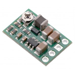
The compact (0.4″ × 0.5″) D24V5F15 synchronous buck voltage regulator takes an input voltage of up to 36 V and efficiently reduces it to 15 V while allowing for a maximum output current of 500 mA. Pololu 2847
This small synchronous switching step-down (or buck) regulator takes an input voltage of up to 38 V and efficiently reduces it to 7.5 V. The board measures only 0.7″ × 0.7″, but it allows a typical continuous output current of up to 2.5 A. Typical efficiencies of 85% to 95% make this regulator well suited for powering moderate loads like sensors or small motors.
Step-Down DC-DC converter module based on the D36V6F3 system. Input voltage 4 ... 50V, output voltage 3.3V (max. 600mA). Polol 3791
Step-Down converter D36V50F5 with an output voltage of 5 V, an input voltage from 5.5 to 50 V and a maximum output current of 8 A. Pololu 4091
Step-down converter with adjustable output voltage 1.2V-35V and current efficiency 9A. The module allows to limit the current consumption at the output via a multi-turn potentiometer. modxl4016sd
No product available!
Step-Down Voltage Regulator D24V25F5. Pololu 2850