


")

zł28.57 tax excl.
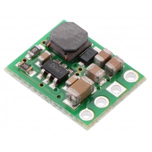
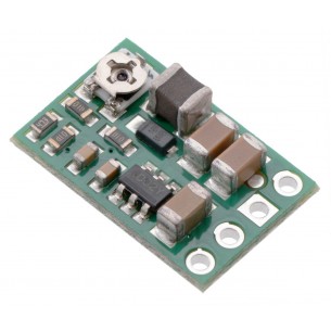
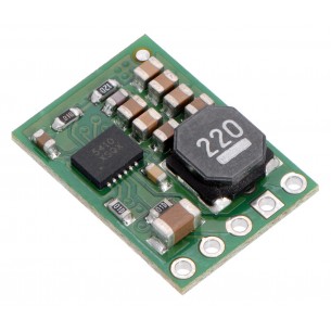
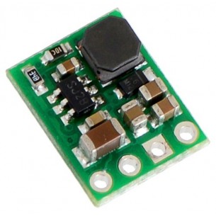
This compact (0.4″ × 0.5″) switching step-down (or buck) voltage regulator takes input voltages up to 50 V and efficiently reduces them to 15 V while allowing for a maximum output current of 600 mA. It has a very low dropout, so it can be used with input voltages that are within a few hundred millivolts of its output.

free shipping in Poland for all orders over 500 PLN

If your payment will be credited to our account by 11:00

Each consumer can return the purchased goods within 14 days
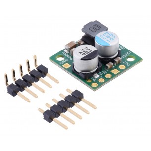
The pins have a 0.1″ spacing, making this board compatible with standard solderless breadboards and perfboards.
The D36V6x family of buck (step-down) voltage regulators generates lower output voltages from input voltages as high as 50 V. They are switching regulators (also called switched-mode power supplies (SMPS) or DC-to-DC converters), which makes them much more efficient than linear voltage regulators, especially when the difference between the input and output voltage is large. This family includes seven versions with fixed output voltages ranging from 3.3 V to 15 V and two adjustable versions that can be set using a trimmer potentiometer:
The regulators feature short-circuit/over-current protection, and thermal shutdown helps prevent damage from overheating. The boards do not have reverse-voltage protection.
This regulator has four connections: shutdown (SHDN), input voltage (VIN), ground (GND), and output voltage (VOUT).
The SHDN pin can be driven low (under 1.25 V) to turn off the output and put the board into a low-power state (< 2 μA typical). The regulator is enabled by default, and this input can be left disconnected if you do not need this feature.
The input voltage, VIN, powers the regulator. Voltages between 4 V and 50 V can be applied to VIN, but for versions of the regulator that have an output voltage higher than 4 V, the effective lower limit of VIN is VOUT plus the regulator’s dropout voltage, which varies approximately linearly with the load (see below for graphs of the dropout voltage as a function of the load). Additionally, please be wary of destructive LC spikes (see below for more information).
The four connections are labeled on the back side of the PCB and are arranged with a 0.1″ spacing along the edge of the board for compatibility with solderless breadboards, connectors, and other prototyping arrangements that use a 0.1″ grid. You can solder wires directly to the board or solder in either the 4×1 straight male header strip or the 4×1 right-angle male header strip that is included.
The efficiency of a voltage regulator, defined as (Power out)/(Power in), is an important measure of its performance, especially when battery life or heat are concerns.
The maximum achievable output current of these regulators varies with the input voltage but also depends on other factors, including the ambient temperature, air flow, and heat sinking. The graph below shows maximum output currents that these regulators can deliver continuously at room temperature in still air and without additional heat sinking.
The quiescent current is the current the regulator uses just to power itself, and the graph below shows this for the different regulator versions as a function of the input voltage. The module’s SHDN input can be driven low to put the board into a low-power state where it typically draws under 2 μA.
The dropout voltage of a step-down regulator is the minimum amount by which the input voltage must exceed the regulator’s target output voltage in order to ensure the target output can be achieved. For example, if a 5 V regulator has a 1 V dropout voltage, the input must be at least 6 V to ensure the output is the full 5 V. Generally speaking, the dropout voltage increases as the output current increases.
When connecting voltage to electronic circuits, the initial rush of current can cause voltage spikes that are much higher than the input voltage. If these spikes exceed the regulator’s maximum voltage (50 V), the regulator can be destroyed. In our tests with typical power leads (~30″ test clips), input voltages above 28 V caused spikes over 50 V.
If you are connecting more than 28 V or your power leads or supply has high inductance, we recommend soldering a suitably rated 33 μF or larger electrolytic capacitor close to the regulator between VIN and GND.
| Size: | 0.4″ × 0.5″ × 0.1″1 |
|---|---|
| Weight: | 0.5 g1 |
Data sheet
Step-Down DC-DC converter module based on the D36V6F3 system. Input voltage 4 ... 50V, output voltage 3.3V (max. 600mA). Polol 3791
Step-Down DC-DC converter module based on the D36V6F5 chip. Input voltage 5.2..50V, output voltage 5V (max. 600mA). Pololu 3792
Step-Down DC-DC converter module based on the D36V6F6 chip. Input voltage 6.2..50V, output voltage 6V (max. 600mA). Pololu 3793
This compact (0.4″ × 0.5″) switching step-down (or buck) voltage regulator takes input voltages up to 50 V and efficiently reduces them to 7.5 V while allowing for a maximum output current of 600 mA. It has a very low dropout, so it can be used with input voltages that are within a few hundred millivolts of its output.
This compact (0.4″ × 0.5″) switching step-down (or buck) voltage regulator takes input voltages up to 50 V and efficiently reduces them to 9 V while allowing for a maximum output current of 600 mA. It has a very low dropout, so it can be used with input voltages that are within a few hundred millivolts of its output.
Step-Down DC-DC converter module based on the D36V6F12 system. Input voltage 12.2.50V, output voltage 12V (max. 600mA). Pololu 3796
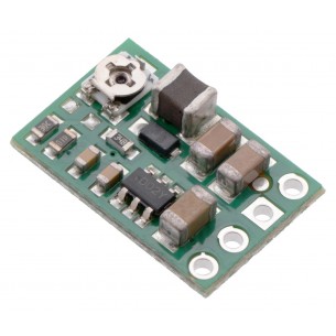
This compact (0.4″ × 0.5″) switching step-down (or buck) voltage regulator takes input voltages between 4 V and 50 V and efficiently reduces them to a lower, user-adjustable voltage set by an on-board trimmer potentiometer. It has an output voltage range of 2.5 V to 7.5 V and a maximum output current of 600 mA.
No product available!
This compact switching step-down voltage regulator. It has an output voltage range of 4 V to 25 V and a maximum output current of 600 mA. Pololu 3799
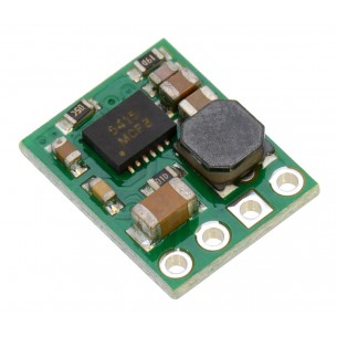
This small synchronous switching step-down (or buck) regulator takes an input voltage from 4 V to 36 V and efficiently reduces it to 3.3 V. The board measures only 0.7″ × 0.7″ yet delivers a typical continuous output current of up to 2.6 A and features reverse voltage protection.
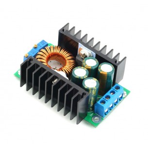
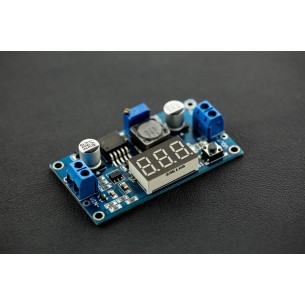
Step-down converter with adjustable output voltage 1.2V-35V and current efficiency 9A. The module allows to limit the current consumption at the output via a multi-turn potentiometer. modxl4016sd
No product available!
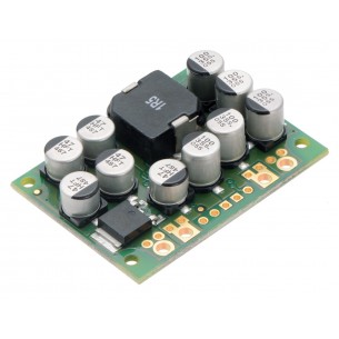
Step-Down DC-DC converter module based on the D24V150F12 chip. Input voltage 14.5 ... 40V, output voltage 12V (max 15A). Pololu 2885
Step-Down DC-DC converter module based on the D36V6F3 system. Input voltage 4 ... 50V, output voltage 3.3V (max. 600mA). Polol 3791
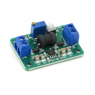
The Step Down DC-DC converter module (MP2307) allows to obtain 0.93..18V output voltage at 4.75..24V input voltage. The output voltage is regulated by a potentiometer
DFR0379
The compact (0.4″ × 0.5″) D24V5F1 synchronous buck voltage regulator takes input voltages between 3 V and 36 V and efficiently reduces them to 1.8 V while allowing for a maximum output current of 500 mA. This regulator offers typical efficiencies between 75% and 90%. The pins have a 0.1″ spacing, making this board compatible with standard solderless breadboards and perfboards.
Step-Down DC-DC converter module based on the D24V150F7 chip. Input voltage 9..40V, output voltage 7.5V (max 15A). Pololu 2883
No product available!
No product available!
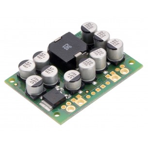
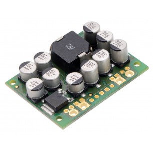
This synchronous switching step-down (or buck) regulator takes an input voltage of up to 40V and efficiently reduces it to 5V with an available output current of around 15A. Typical efficiencies of 80% to 95% along with its high current capabilities make this regulator well suited for powering large loads. Pololu 2881
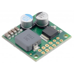
Step-Down converter D36V50F7 with an output voltage of 7.5 V, an input voltage from 8.3 to 50 V and a maximum output current of 7 A. Pololu 4093
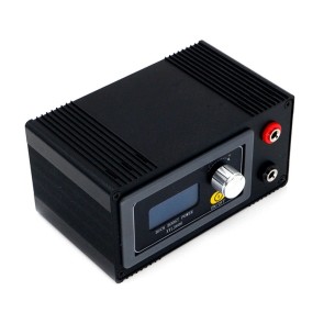
A power supply based on a DC-DC converter with a current capacity of up to 6.1 A. The input voltage can range from 6 V to 30 V, while the output voltage is adjustable from 0 V to 36 V. Enclosure version. XYL3606S
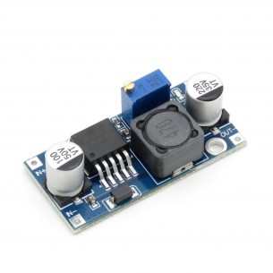
Step Down DC-DC converter module based on LM2596 circuit, input voltage 3-40V, regulated output voltage 1.5--35V
The Step-Down D24V3F9 Buck Voltage Regulator module gives the output voltage of 9V with a wide input voltage range of 11-42V and a maximum output current of 300 mA. Pololu 2099
No product available!
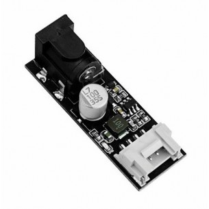
DC-DC Step-Down Converter ME3116AM6G with an output voltage of 5 V, input voltage from 6 to 24 V and a maximum output current of 1 A. Dedicated to the M5Stack modules. M5Stack U125
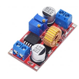
Step-Down XL4015 converter module with adjustable output voltage in the range from 1.25 to 36 V with a wide input voltage range from 4 to 38 V and a maximum output current of 5 A
This compact (0.4″ × 0.5″) switching step-down (or buck) voltage regulator takes input voltages up to 50 V and efficiently reduces them to 15 V while allowing for a maximum output current of 600 mA. It has a very low dropout, so it can be used with input voltages that are within a few hundred millivolts of its output.