


")

zł29.14 tax excl.
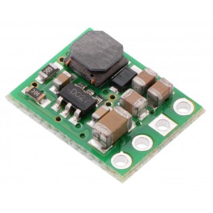
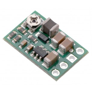
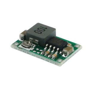
This compact (0.4″ × 0.5″) switching step-down (or buck) voltage regulator takes input voltages between 4 V and 50 V and efficiently reduces them to a lower, user-adjustable voltage set by an on-board trimmer potentiometer. It has an output voltage range of 2.5 V to 7.5 V and a maximum output current of 600 mA.
It has a very low dropout, so it can be used with input voltages that are within a few hundred millivolts of its output. The pins have a 0.1″ spacing, making this board compatible with standard solderless breadboards and perfboards.
The D36V6x family of buck (step-down) voltage regulators generates lower output voltages from input voltages as high as 50 V. They are switching regulators (also called switched-mode power supplies (SMPS) or DC-to-DC converters), which makes them much more efficient than linear voltage regulators, especially when the difference between the input and output voltage is large. This family includes seven versions with fixed output voltages ranging from 3.3 V to 15 V and two adjustable versions that can be set using a trimmer potentiometer:
The regulators feature short-circuit/over-current protection, and thermal shutdown helps prevent damage from overheating. The boards do not have reverse-voltage protection.
This regulator has four connections: shutdown (SHDN), input voltage (VIN), ground (GND), and output voltage (VOUT).
The SHDN pin can be driven low (under 1.25 V) to turn off the output and put the board into a low-power state (< 2 μA typical). The regulator is enabled by default, and this input can be left disconnected if you do not need this feature.
The input voltage, VIN, powers the regulator and should be between 4 V and 50 V. If the input voltage gets too close to the output voltage, the output will start to drop, so you should ensure that VIN exceeds VOUT by at least the dropout voltage, which varies with the output voltage and the load (see below for graphs of the dropout voltage as a function of the load). Additionally, please be wary of destructive LC spikes (see below for more information).
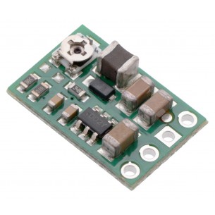
The output voltage, VOUT, is determined by the trimmer potentiometer position, with clockwise turns increasing the output voltage. You can use a multimeter to measure the output as you set it. Please note that the output voltage can be affected by a screwdriver touching the potentiometer, so the output measurement should be done with nothing touching the potentiometer. When setting the output voltage, note that the buck regulator can only produce voltages lower than the input voltage. The following graph shows approximately how the potentiometer position maps to the output voltage settings on the D36V6ALV (blue curve) and D36V6AHV (red curve).
The four connections are labeled on the back side of the PCB and are arranged with a 0.1″ spacing along the edge of the board for compatibility with solderless breadboards, connectors, and other prototyping arrangements that use a 0.1″ grid. You can solder wires directly to the board or solder in either the 4×1 straight male header strip or the 4×1 right-angle male header strip that is included.
The efficiency of a voltage regulator, defined as (Power out)/(Power in), is an important measure of its performance, especially when battery life or heat are concerns.
The maximum achievable output current of these regulators varies with the input voltage but also depends on other factors, including the ambient temperature, air flow, and heat sinking. The graph below shows maximum output currents that these regulators can deliver continuously at room temperature in still air and without additional heat sinking.
The quiescent current is the current the regulator uses just to power itself, and the graph below shows this for the different regulator versions as a function of the input voltage. The module’s SHDN input can be driven low to put the board into a low-power state where it typically draws under 2 μA.
The dropout voltage of a step-down regulator is the minimum amount by which the input voltage must exceed the regulator’s target output voltage in order to ensure the target output can be achieved. For example, if a 5 V regulator has a 1 V dropout voltage, the input must be at least 6 V to ensure the output is the full 5 V. Generally speaking, the dropout voltage increases as the output current increases.
When connecting voltage to electronic circuits, the initial rush of current can cause voltage spikes that are much higher than the input voltage. If these spikes exceed the regulator’s maximum voltage (50 V), the regulator can be destroyed. In our tests with typical power leads (~30″ test clips), input voltages above 28 V caused spikes over 50 V.
If you are connecting more than 28 V or your power leads or supply has high inductance, we recommend soldering a suitably rated 33 μF or larger electrolytic capacitor close to the regulator between VIN and GND.
| Size: | 0.4″ × 0.6″ × 0.15″1 |
|---|---|
| Weight: | 0.6 g1 |
| Minimum operating voltage: | 4 V2 |
|---|---|
| Maximum operating voltage: | 50 V |
| Maximum output current: | 600 mA |
| Minimum output voltage: | 2.5 V3 |
| Maximum output voltage: | 7.5 V3 |
| Reverse voltage protection?: | N |
| Maximum quiescent current: | 2 mA4 |
| Output type: | adjustable 2.5-7.5V3 |
| PCB dev codes: | reg04a |
|---|---|
| Other PCB markings: | 0J3866 |
Data sheet
Manufacturer BTC Korporacja sp. z o. o. Lwowska 5 05-120 Legionowo Poland sprzedaz@kamami.pl 22 767 36 20
Responsible person BTC Korporacja sp. z o. o. Lwowska 5 05-120 Legionowo Poland sprzedaz@kamami.pl 22 767 36 20
Step-Down DC-DC converter module based on the D36V6F3 system. Input voltage 4 ... 50V, output voltage 3.3V (max. 600mA). Polol 3791
Step-Down DC-DC converter module based on the D36V6F5 chip. Input voltage 5.2..50V, output voltage 5V (max. 600mA). Pololu 3792
Step-Down DC-DC converter module based on the D36V6F6 chip. Input voltage 6.2..50V, output voltage 6V (max. 600mA). Pololu 3793
No product available!
This compact (0.4″ × 0.5″) switching step-down (or buck) voltage regulator takes input voltages up to 50 V and efficiently reduces them to 7.5 V while allowing for a maximum output current of 600 mA. It has a very low dropout, so it can be used with input voltages that are within a few hundred millivolts of its output.
This compact (0.4″ × 0.5″) switching step-down (or buck) voltage regulator takes input voltages up to 50 V and efficiently reduces them to 9 V while allowing for a maximum output current of 600 mA. It has a very low dropout, so it can be used with input voltages that are within a few hundred millivolts of its output.
Step-Down DC-DC converter module based on the D36V6F12 system. Input voltage 12.2.50V, output voltage 12V (max. 600mA). Pololu 3796
This compact (0.4″ × 0.5″) switching step-down (or buck) voltage regulator takes input voltages up to 50 V and efficiently reduces them to 15 V while allowing for a maximum output current of 600 mA. It has a very low dropout, so it can be used with input voltages that are within a few hundred millivolts of its output.
This compact switching step-down voltage regulator. It has an output voltage range of 4 V to 25 V and a maximum output current of 600 mA. Pololu 3799
Step-Down DC-DC converter module based on the D36V6F6 chip. Input voltage 6.2..50V, output voltage 6V (max. 600mA). Pololu 3793
No product available!
This compact (0.4″ × 0.5″) switching step-down (or buck) voltage regulator takes input voltages up to 50 V and efficiently reduces them to 7.5 V while allowing for a maximum output current of 600 mA. It has a very low dropout, so it can be used with input voltages that are within a few hundred millivolts of its output.
This compact (0.4″ × 0.5″) switching step-down (or buck) voltage regulator takes input voltages up to 50 V and efficiently reduces them to 9 V while allowing for a maximum output current of 600 mA. It has a very low dropout, so it can be used with input voltages that are within a few hundred millivolts of its output.
Step-Down DC-DC converter module based on the D36V6F12 system. Input voltage 12.2.50V, output voltage 12V (max. 600mA). Pololu 3796
This compact (0.4″ × 0.5″) switching step-down (or buck) voltage regulator takes input voltages up to 50 V and efficiently reduces them to 15 V while allowing for a maximum output current of 600 mA. It has a very low dropout, so it can be used with input voltages that are within a few hundred millivolts of its output.
This compact (0.4″ × 0.5″) switching step-down (or buck) voltage regulator takes input voltages between 4 V and 50 V and efficiently reduces them to a lower, user-adjustable voltage set by an on-board trimmer potentiometer. It has an output voltage range of 2.5 V to 7.5 V and a maximum output current of 600 mA.
No product available!
This compact switching step-down voltage regulator. It has an output voltage range of 4 V to 25 V and a maximum output current of 600 mA. Pololu 3799
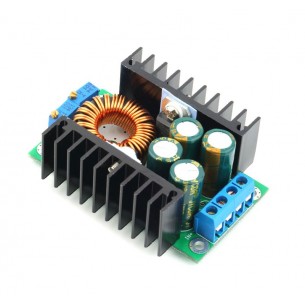
Step-down converter with adjustable output voltage 1.2V-35V and current efficiency 9A. The module allows to limit the current consumption at the output via a multi-turn potentiometer. modxl4016sd
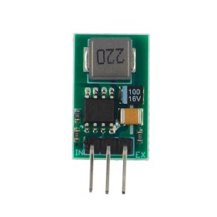
DC-DC Step-Down converter module with 5V output voltage and 1A output current. The module can be a replacement for the popular LM7805 regulator.
Step-Down converter module with input voltage from 4.75 to 23V, output voltage from 1 to 17V and output current 1.8 A (3 A instantaneous current).
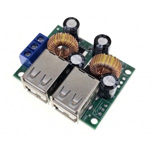
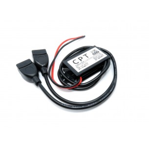
Step Down converter module with an output voltage of 5 V and a maximum current of 2x2,5 A. The board is equipped with four USB connectors
No product available!
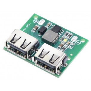
Step Down converter module with an output voltage of 5 V and a maximum current of 3 A. The board is equipped with two USB connectors
No product available!
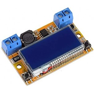
Power supply based on DC Step Down converter with adjustable output voltage from 0 to 16.5 V and current efficiency of 3 A. The set includes LCD display and transparent case
No product available!
Waterproof DC-DC Step-Down Converter with 8 to 22V input voltage and 5V 3A USB output
No product available!
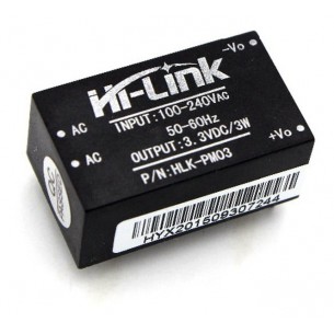
Modular power supply with a power of 3 W, input voltage from 100 to 240 V and output voltage of 3.3 V. Designed for mounting on a PCB. Hi-Link HLK-PM03
No product available!
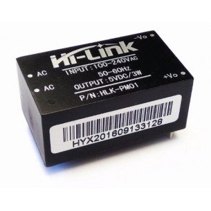
Modular power supply with a power of 3 W, input voltage from 100 to 240 V and output voltage of 5 V. Designed for mounting on a PCB. Hi-Link HLK-PM01
No product available!
This compact (0.4″ × 0.5″) switching step-down (or buck) voltage regulator takes input voltages between 4 V and 50 V and efficiently reduces them to a lower, user-adjustable voltage set by an on-board trimmer potentiometer. It has an output voltage range of 2.5 V to 7.5 V and a maximum output current of 600 mA.