


zł28.87 tax excl.
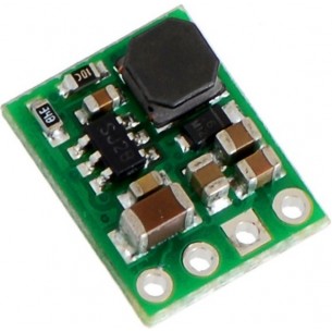
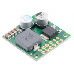
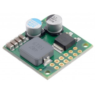
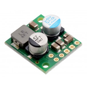
The compact (0.4″ × 0.5″) D24V5F1 synchronous buck voltage regulator takes input voltages between 3 V and 36 V and efficiently reduces them to 1.8 V while allowing for a maximum output current of 500 mA. This regulator offers typical efficiencies between 75% and 90%. The pins have a 0.1″ spacing, making this board compatible with standard solderless breadboards and perfboards.
The D24V5Fx family of buck (step-down) voltage regulators generates lower output voltages from input voltages as high as 36 V. They are switching regulators (also called switched-mode power supplies (SMPS) or DC-to-DC converters) and have a typical efficiency between 80% to 93%, which is much more efficient than linear voltage regulators, especially when the difference between the input and output voltage is large. These regulators have a power-save mode that activates at light loads and a low quiescent (no load) current draw, which make them well suited for low-power applications that are run from a battery.
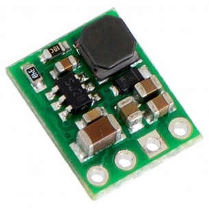
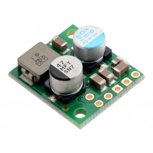
The different versions of this regulator all look very similar, so the bottom silkscreen includes a blank space where you can add your own distinguishing marks or labels. This product page applies to all eight versions of the D24V5Fx family.
The regulators feature short-circuit/over-current protection, and thermal shutdown helps prevent damage from overheating. The boards do not have reverse-voltage protection.
The picture on the right shows a 1 A D24V10Fx regulator next to a 0.5 A D24V5Fx regulator and a common 7805 linear regulator in a TO-220 package.
The buck regulator has four connections: shutdown (SHDN), input voltage (VIN), ground (GND), and output voltage (VOUT).
The SHDN pin can be driven low (under 0.4 V) to turn off the output and put the board into a low-power state. There is a 100 kΩ pull-up resistor between the SHDN pin and VIN, so if you want to leave the board permanently enabled, the SHDNpin can be left disconnected. While the SHDN pin is being driven low, the current draw of the regulator is dominated by the current through the pull-up resistor and will be proportional to the input voltage. (At 36 V in it will draw about 360 μA.)
The input voltage, VIN, powers the regulator. Voltages between 3 V and 36 V can be applied to VIN, but for versions of the regulator that have an output voltage higher than 3 V, the effective lower limit of VIN is VOUT plus the regulator’s dropout voltage, which varies approximately linearly with the load (see below for graphs of dropout voltages as a function of the load). Additionally, please be wary of destructive LC spikes (see below for more information).
The output voltage, VOUT, is fixed and depends on the regulator version: the D24V5F1 version outputs 1.5 V, D24V5F2 version outputs 2.5 V, the D24V5F3 version outputs 3.3 V, the D24V5F5 version outputs 5 V, the D24V5F6 version outputs 6 V, the D24V5F9 version outputs 9 V, the D24V5F12 version outputs 12 V, and the D24V5F15 version outputs 15 V
The four connections are labeled on the back side of the PCB and are arranged with a 0.1″ spacing along the edge of the board for compatibility with solderless breadboards, connectors, and other prototyping arrangements that use a 0.1″ grid. You can solder wires directly to the board or solder in either the 4×1 straight male header strip or the 4×1 right-angle male header strip that is included.
The efficiency of a voltage regulator, defined as (Power out)/(Power in), is an important measure of its performance, especially when battery life or heat are concerns. This family of switching regulators typically has an efficiency of 80% to 95%, though the actual efficiency in a given system depends on input voltage, output voltage, and output current. See the efficiency graph near the bottom of this page for more information.
In order to achieve a high efficiency at low loads, this regulator automatically goes into a power-save mode where the switching frequency is reduced. In power-save mode, the switching frequency of the regulator changes as necessary to minimize power loss. This could make it harder to filter out noise on the output caused by switching.
The dropout voltage of a step-down regulator is the minimum amount by which the input voltage must exceed the regulator’s target output voltage in order to ensure the target output can be achieved. For example, if a 5 V regulator has a 1 V dropout voltage, the input must be at least 6 V to ensure the output is the full 5 V. Generally speaking, the dropout voltage increases as the output current increases. See the “Details” section below for more information on the dropout voltage for this specific regulator version.
Since this regulator’s has a minimum input voltage of 3 V is well above its 1.8 V output, dropout voltage is not a concern for this version of the regulator: for any load within the 500 mA maximum, an input voltage of 3 V will result in an output of 1.8 V.
When connecting voltage to electronic circuits, the initial rush of current can cause voltage spikes that are much higher than the input voltage. If these spikes exceed the regulator’s maximum voltage (36 V), the regulator can be destroyed. In our tests with typical power leads (~30″ test clips), input voltages above 20 V caused spikes over 36 V.
If you are connecting more than 20 V or your power leads or supply has high inductance, we recommend soldering a 33 μF or larger electrolytic capacitor close to the regulator between VIN and GND. The capacitor should be rated for at least 50 V.
| Size: | 0.4″ × 0.5″ × 0.1″1 |
|---|---|
| Weight: | 0.6 g1 |
| Minimum operating voltage: | 3 V |
|---|---|
| Maximum operating voltage: | 36 V |
| Maximum output current: | 500 mA |
| Output voltage: | 1.8 V |
| Reverse voltage protection?: | N |
| Maximum quiescent current: | 0.2 mA2 |
| PCB dev codes: | reg16a |
|---|---|
| Other PCB markings: | 0J7990, blank white box |
Data sheet
Manufacturer BTC Korporacja sp. z o. o. Lwowska 5 05-120 Legionowo Poland sprzedaz@kamami.pl 22 767 36 20
Responsible person BTC Korporacja sp. z o. o. Lwowska 5 05-120 Legionowo Poland sprzedaz@kamami.pl 22 767 36 20
The Step-Down D24V3F5 Buck Voltage Regulator module gives the output voltage of 5V with a wide input voltage range of 7-42V and a maximum output current of 300 mA. Pololu 2098
The Step-Down D24V3F3 Buck Voltage Regulator module gives the output voltage of 3,3V with a wide input voltage range of 4.3-42V and a maximum output current of 300 mA. Pololu 2097
The Step-Down D24V6F5 Buck Voltage Regulator module gives the output voltage of 5V with a wide input voltage range of 7-42V and a maximum output current of 600 mA. Pololu 2107
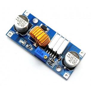
Step-Down converter with an output voltage of 5 V, an input voltage of 7 to 26 V and a maximum current of 3 A
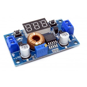
Step-Down converter with adjustable output voltage from 1.25 to 36 V, input voltage from 4 to 38 V and maximum current up to 5 A. Board equipped with a voltmeter with display
No product available!
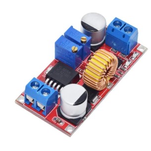
Step-Down converter with adjustable output voltage from 1.25 to 36 V, input voltage from 4 to 38 V and maximum current up to 5 A
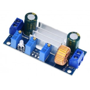
Step-Down XL4015 converter module with adjustable output voltage in the range from 1.25 to 33 V with a wide input voltage range from 4 to 35 V and a maximum output current of 5 A
No product available!
Step-Down XL4005 converter module with adjustable output voltage in the range from 0.8 to 30 V with a wide input voltage range from 4.5 to 30 V and a maximum output current of 5 A
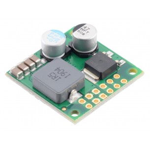
Step-Down converter D36V50F3 with an output voltage of 3.3 V, an input voltage from 4.5 to 50 V and a maximum output current of 9.5 A. Pololu 4090
Step-Down converter D36V50F5 with an output voltage of 5 V, an input voltage from 5.5 to 50 V and a maximum output current of 8 A. Pololu 4091
Step-Down converter D36V50F6 with an output voltage of 6 V, an input voltage from 6.5 to 50 V and a maximum output current of 8 A. Pololu 4092
Step-Down converter D36V50F7 with an output voltage of 7.5 V, an input voltage from 8.3 to 50 V and a maximum output current of 7 A. Pololu 4093
Step-Down converter D36V50F9 with an output voltage of 9 V, an input voltage from 9.9 to 50 V and a maximum output current of 7 A. Pololu 4094
No product available!
Step-Down converter D36V50F12 with an output voltage of 12 V, an input voltage from 13.3 to 50 V and a maximum output current of 6.5 A. Pololu 4095
Step-Down converter D36V28F3 with an output voltage of 3.3 V, an input voltage from 4.5 to 50 V and a maximum output current of 4.5 A. Pololu 3781
No product available!
Step-Down converter D36V28F5 with an output voltage of 5 V, an input voltage from 5.3 to 50 V and a maximum output current of 4 A. Pololu 3782
Step-Down converter D36V28F6 with an output voltage of 6 V, an input voltage from 6.3 to 50 V and a maximum output current of 4 A. Pololu 3783
Step-Down converter D36V28F7 with an output voltage of 7.5 V, an input voltage from 8 to 50 V and a maximum output current of 3.7 A. Pololu 3784
Step-Down converter D36V28F9 with an output voltage of 9 V, an input voltage from 9.8 to 50 V and a maximum output current of 3.4 A. Pololu 3785
The compact (0.4″ × 0.5″) D24V5F1 synchronous buck voltage regulator takes input voltages between 3 V and 36 V and efficiently reduces them to 1.8 V while allowing for a maximum output current of 500 mA. This regulator offers typical efficiencies between 75% and 90%. The pins have a 0.1″ spacing, making this board compatible with standard solderless breadboards and perfboards.