


zł70.92 tax excl.
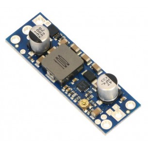
This small synchronous switching step-down (or buck) regulator takes an input voltage of up to 36 V and efficiently reduces it to 7.5 V. The board measures only 0.7″ × 0.7″ yet delivers a typical continuous output current of up to 2.4 A and features reverse voltage protection.
These regulators have a typical quiescent (no load) current draw of around 1 mA, and an enable pin can be used to put the boards in a low-power state that reduces the quiescent current to approximately 5 µA to 10 µA per volt on VIN.The D24V22Fx family of step-down voltage regulators generates lower output voltages from input voltages as high as 36 V. They are synchronous switching regulators (also called switched-mode power supplies (SMPS) or DC-to-DC converters) with typical efficiencies of 85% to 95%, which is much more efficient than linear voltage regulators, especially when the difference between the input and output voltage is large. These regulators can typically support continuous output currents of over 2 A, though the actual available output current is a function of the input voltage and efficiency (see the Typical efficiency and output current section below). In general, the available output current is a little higher for the lower-voltage versions than it is for the higher-voltage versions, and it decreases as the input voltage increases.
The modules have built-in reverse-voltage protection, short-circuit protection, a thermal shutdown feature that helps prevent damage from overheating, and a soft-start feature that reduces inrush current.
The different voltage versions of this regulator all look very similar, so you should consider adding your own distinguishing marks or labels if you will be working simultaneously with multiple versions. This product page applies to all versions of the D24V22Fx family.
The D24V22Fx family is intended to replace our older D24V25Fx family of step-down voltage regulators. The two designs have the same size and similar current capabilities and input voltage ranges, but they do not have the same pinout and are based on different internal circuits, so there are fundamental differences in operation. In particular, these newer D24V22Fx regulators have much lower dropout voltages and provide a “power good” signal, and the newer design allows for higher output voltages (e.g. 12 V).
These buck regulators have five main connection points for five different electrical nodes: power good (PG), enable (EN), input voltage (VIN), ground (GND), and output voltage (VOUT). The board also features a second ground connection point off the main row of connections that might be convenient for applications where you are soldering wires directly to the board rather than using it in a breadboard.
The output voltage, VOUT, is fixed and depends on the regulator version: the D24V22F3 version outputs 3.3 V, the D24V22F5 version outputs 5 V, the D24V22F6 version outputs 6 V, the D24V22F7 version outputs 7.5 V, the D24V22F9 version outputs 9 V, and the D24V22F12 version outputs 12 V.The input voltage, VIN, powers the regulator. Voltages between 4 V and 36 V can be applied to VIN, but for versions of the regulator that have an output voltage higher than 4 V, the effective lower limit of VIN is VOUT pluse the regulator’s dropout voltage, which varies approximately linearly with the load (see below for a graph of dropout voltages as a function of the load).
The regulator is enabled by default: a 270 kΩ pull-up resistor on the board connects the EN pin to reverse-protected VIN. The EN pin can be driven low (under 1 V) to put the board into a low-power state. The quiescent current draw in this sleep mode is dominated by the current in the pull-up resistor from EN to VIN and by the reverse-voltage protection circuit, which altogether will draw between 5 µA and 10 µA per volt on VIN when EN is held low. If you do not need this feature, you should leave the EN pin disconnected.
The “power good” indicator, PG, is an open-drain output that goes low when the regulator’s output voltage falls below around 85% of the nominal voltage and becomes high-impedance when the output voltage rises above around 90%. An external pull-up resistor is required to use this pin.
Typical efficiency and output current:The board has two 0.086″ (2.18 mm) diameter mounting holes intended for #2 or M2 screws. The mounting holes are at opposite corners of the board and are separated by 0.52″ (13.21 mm) both horizontally and vertically. For all the board dimensions, see the dimension diagram (204k pdf).
The efficiency of a voltage regulator, defined as (Power out)/(Power in), is an important measure of its performance, especially when battery life or heat are concerns. This family of switching regulators typically has an efficiency of 85% to 95%, though the actual efficiency in a given system depends on input voltage, output voltage, and output current. See the efficiency graph near the bottom of this page for more information.
The maximum achievable output current is typically over 2 A, but this depends on many factors, including the ambient temperature, air flow, heat sinking, and the input and output voltage.
The dropout voltage of a step-down regulator is the minimum amount by which the input voltage must exceed the regulator’s target output voltage in order to ensure the target output can be achieved. For example, if a 5 V regulator has a 1 V dropout voltage, the input must be at least 6 V to ensure the output is the full 5 V. Generally speaking, the dropout voltage increases as the output current increases. See the “Details” section below for more information on the dropout voltage for this specific regulator version.
During normal operation, this product can get hot enough to burn you. Take care when handling this product or other components connected to it.
| Size: | 0.7″ × 0.7″ × 0.31″1 |
|---|---|
| Weight: | 2.3 g1 |
| Minimum operating voltage: | 8.0 V2 |
|---|---|
| Maximum operating voltage: | 36 V |
| Continuous output current: | 2.4 A3 |
| Output voltage: | 7.5 V |
| Reverse voltage protection?: | Y |
| Maximum quiescent current: | 3 mA4 |
| PCB dev codes: | reg19a |
|---|---|
| Other PCB markings: | 0J9251 |
Data sheet
Manufacturer BTC Korporacja sp. z o. o. Lwowska 5 05-120 Legionowo Poland sprzedaz@kamami.pl 22 767 36 20
Responsible person BTC Korporacja sp. z o. o. Lwowska 5 05-120 Legionowo Poland sprzedaz@kamami.pl 22 767 36 20
The Step-Down D24V3F9 Buck Voltage Regulator module gives the output voltage of 9V with a wide input voltage range of 11-42V and a maximum output current of 300 mA. Pololu 2099
No product available!
The Step-Down D24V6F9 Buck Voltage Regulator module gives the output voltage of 9V with a wide input voltage range of 11.5-42V and a maximum output current of 600 mA. Pololu 2108
No product available!
Pololu 6V Step-Up Voltage Regulator U3V50F6
Pololu Adjustable 4-12V Step-Up Voltage Regulator U3V50ALV
No product available!
Pololu 24V Step-Up Voltage Regulator U3V50F24
The Step-Down D24V6F5 Buck Voltage Regulator module gives the output voltage of 5V with a wide input voltage range of 7-42V and a maximum output current of 600 mA. Pololu 2107
This powerful boost regulator efficiently boosts input voltages as low as 2.9 V to a higher, adjustable output voltage between 9 V and 30 V while allowing an input current as high as 5 A.
No product available!
The Step-Down D24V6F3 Buck Voltage Regulator module gives the output voltage of 3.3V with a wide input voltage range of 4.8-42V and a maximum output current of 600 mA. Pololu 2106
The Step-Down D24V6F9 Buck Voltage Regulator module gives the output voltage of 9V with a wide input voltage range of 11.5-42V and a maximum output current of 600 mA. Pololu 2108
No product available!
The Step-Down D24V6F12 Buck Voltage Regulator module gives the output voltage of 12V with a wide input voltage range of 15-42V and a maximum output current of 600 mA. Pololu 2109
No product available!
No product available!
The Step-Up / Step-Down S18V20F12 inverter module gives the output voltage of 12V with a wide input voltage range of 3 ... 30V and a maximum output current of 2A. Polol 2577
No product available!
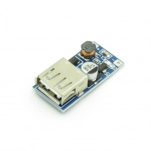
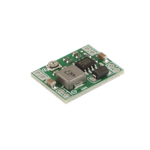
Step-up DC-DC converter module, 0.9-5V input voltage, 5V output voltage (max. 500 mA) connected to the USB socket. There is a diode on the board indicating the power connection
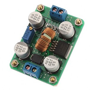
Step DC-DC converter, Uwe 3.5-30 V, adjustable 4-30 V, RoHS
No product available!
Step-up DC-DC converter module based on the LM2587 circuit, input voltage 3.5..30V, regulated output voltage 4..30V. The module is equipped with ARK connectors
No product available!
Przetwornica DC-DC Step Down (MP1584), Uwe 4.5..28V, Uwy regulowane 0.8..20V, RoHS
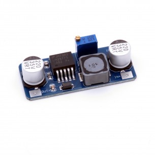
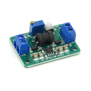
The Step Down DC-DC converter module (MP2307) allows to obtain 0.93..18V output voltage at 4.75..24V input voltage. The output voltage is regulated by a potentiometer
No product available!
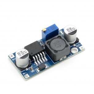
Step Down DC-DC converter module based on LM2596 circuit, input voltage 3-40V, regulated output voltage 1.5--35V
This small synchronous switching step-down (or buck) regulator takes an input voltage of up to 36 V and efficiently reduces it to 7.5 V. The board measures only 0.7″ × 0.7″ yet delivers a typical continuous output current of up to 2.4 A and features reverse voltage protection.