


")

zł13.07 tax excl.
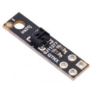
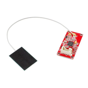
This IR LED/phototransistor pair is great for precisely identifying changes in reflectance. In general, the closer the object, the higher the contrast between light and dark readings, but high-reflectance objects are generally detectable out to around 80 mm.
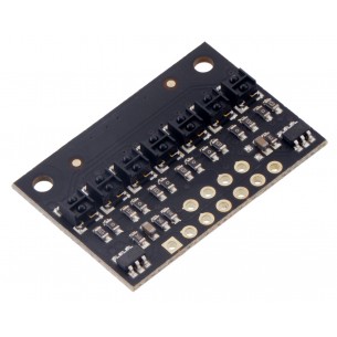
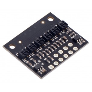
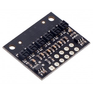
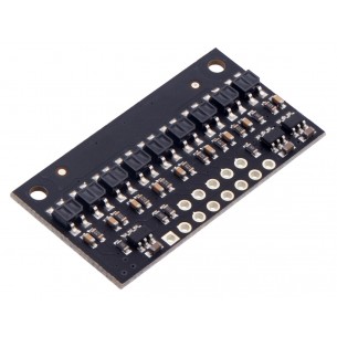
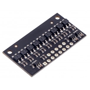
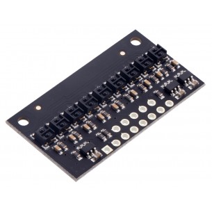
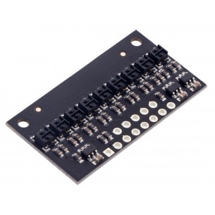
These reflectance sensors feature a linear array of infrared emitter/phototransistor pair modules in a high-density (4 mm pitch) or medium-density (8 mm pitch) arrangement, which makes them well suited for applications that require detection of changes in reflectivity. This change in reflectivity can be due to a color change at a fixed distance, such as when sensing a black line on a white background, as well as due to a change in the distance to or presence of an object in front of the sensor. A variety of sensor counts and densities is available so you can pick the ideal arrangement for your application. Since the outputs are all independent, you can connect just some of the channels to attain an irregular or non-standard sensor spacing.
Unlike our original QTR sensor modules, these units have integrated LED drivers that provide brightness control independent of the supply voltage, which can be anywhere from 2.9 V to 5.5 V, while enabling optional dimming to any of 32 possible brightness settings. For high-density (HD) modules with five or more sensors and medium-density (MD) modules with eleven or more sensors, there are separate controls for the odd-numbered and even-numbered LEDs, which gives you extra options for detecting light reflected at various angles. See the “Emitter control” section below for more information on using this feature.
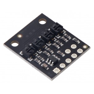
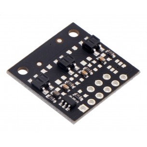
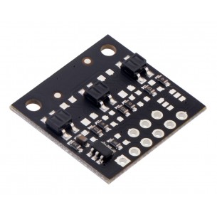
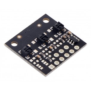
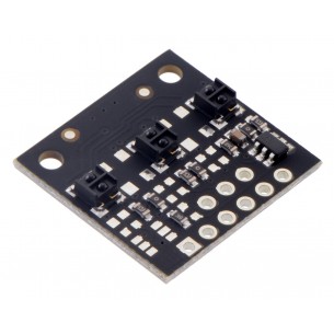
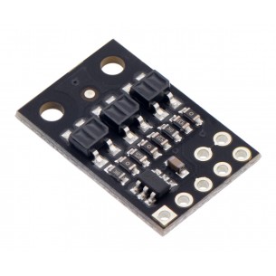
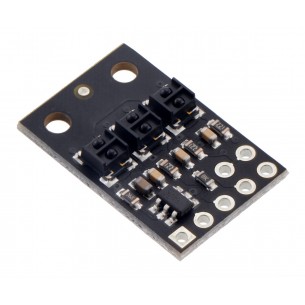
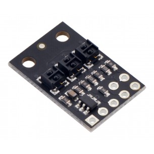
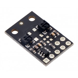
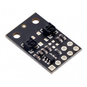
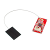
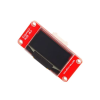
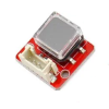
Two different sensor options are available, denoted by “QTR” or “QTRX” in the product name. The “QTR” versions feature lower-cost sensor modules without lenses while the “QTRX” versions feature higher-performance sensor modules with lenses, which allow similar performance at a much lower IR LED current. You can see the two different sensor styles in the pictures below of the 4-channel modules:
Each sensor option is available in two output types: an “A” version with analog voltage outputs between 0 V and VCC, and an “RC” version with outputs that can be read with a digital I/O line on a microcontroller by first setting the lines high and then releasing them and timing how long it takes them to read as low (typically anywhere from a few microseconds to a few milliseconds). The lower the output voltage or shorter the voltage decay time, the higher the reflectance.
Note: Unlike most of our products, these sensor arrays do not ship with any headers or connectors included, so you will need to supply your own or solder wires directly to the board to use it. See our selection of male headers, female headers, and pre-crimped wires for various connector options.
Each sensor on the A versions outputs its reflectance measurement as an analog voltage that can range from 0 V when the reflectance is very strong to VCC when the reflectance is very weak. The typical sequence for reading a sensor is:
This last method will work if you are able to get high reflectance from your white surface as depicted in the left image, but will probably fail if you have a lower-reflectance signal profile like the one on the right.
Each sensor on the RC versions requires a digital I/O line capable of driving the output line high and then measuring the time for the output voltage to decay.
These steps can typically be executed in parallel on multiple I/O lines.
With a strong reflectance, the decay time can be as low as a few microseconds; with no reflectance, the decay time can be up to a few milliseconds. The exact time of the decay depends on your microcontroller’s I/O line characteristics. Meaningful results can be available within 1 ms in typical cases (i.e. when not trying to measure subtle differences in low-reflectance scenarios), allowing up to 1 kHz sampling of all sensors. If lower-frequency sampling is sufficient, you can achieve substantial power savings by turning off the LEDs. For example, if a 100 Hz sampling rate is acceptable, the LEDs can be off 90% of the time, lowering average current consumption from 125 mA to 13 mA.
These reflectance sensor arrays maintain a constant current through their IR emitters, keeping the emitters’ brightness constant, independent of the supply voltage (2.9 V to 5.5 V). The emitters can be controlled with the board’s CTRL pins, and the details of the control depends on the array size and density:
Driving a CTRL pin low for at least 1 ms turns off the associated emitter LEDs, while driving it high (or allowing the board to pull it high) turns on the emitters with the board’s default (full) current, which is 30 mA for “QTR” versions and 3.5 mA for “QTRX” versions. For more advanced use, the CTRL pin can be pulsed low to cycle the associated emitters through 32 dimming levels.
To send a pulse, you should drive the CTRL pin low for at least 0.5 μs (but no more than 300 μs), then high for at least 0.5 μs; (it should remain high after the last pulse). Each pulse causes the driver to advance to the next dimming level, wrapping around to 100% after the lowest-current level. Each dimming level corresponds to a 3.33% reduction in current, except for the last three levels, which represent a 1.67% reduction, as shown in the table below. Note that turning the LEDs off with a >1 ms pulse and then back on resets them to full current.
| Dimming level (pulses) | Emitter current (%) |
Dimming level (pulses) | Emitter current (%) | |
|---|---|---|---|---|
| 0 | 100.00% | 16 | 46.67% | |
| 1 | 96.67% | 17 | 43.33% | |
| 2 | 93.33% | 18 | 40.00% | |
| 3 | 90.00% | 19 | 36.67% | |
| 4 | 86.67% | 20 | 33.33% | |
| 5 | 83.33% | 21 | 30.00% | |
| 6 | 80.00% | 22 | 26.67% | |
| 7 | 76.67% | 23 | 23.33% | |
| 8 | 73.33% | 24 | 20.00% | |
| 9 | 70.00% | 25 | 16.67% | |
| 10 | 66.67% | 26 | 13.33% | |
| 11 | 63.33% | 27 | 10.00% | |
| 12 | 60.00% | 28 | 6.67% | |
| 13 | 56.67% | 29 | 5.00% | |
| 14 | 53.33% | 30 | 3.33% | |
| 15 | 50.00% | 31 | 1.67% |
For example, to reduce the emitter current to 50%, you would apply 15 low pulses to the CTRL pin and then keep it high after the last pulse.
Data sheet
Manufacturer BTC Korporacja sp. z o. o. Lwowska 5 05-120 Legionowo Poland sprzedaz@kamami.pl 22 767 36 20
Responsible person BTC Korporacja sp. z o. o. Lwowska 5 05-120 Legionowo Poland sprzedaz@kamami.pl 22 767 36 20
Module with 7 QTRX type optocoupler with analog output. The module operates from 2.9 V to 5.5 V, detects objects at a distance of up to 40 mm. The sensor will be used in projects that require detection of changes in the ground, e.g. in linefollower robots. Pololu 4407
Module with 4 QTRX type optocoupler with analog output. The module operates from 2.9 V to 5.5 V, detects objects at a distance of up to 40 mm. The sensor will be used in projects that require detection of changes in the ground, e.g. in linefollower robots. Pololu 4404
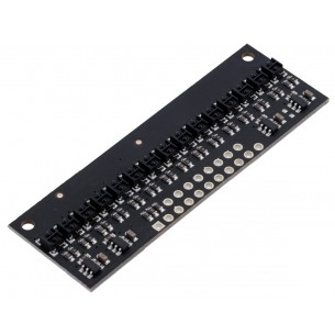
Module with 15 QTRX type optocoupler with analog output. The module operates from 2.9 V to 5.5 V, detects objects at a distance of up to 50 mm. The sensor will be used in projects that require detection of changes in the ground, e.g. in linefollower robots. Pololu 4415
No product available!
Module with 1 QTRX type optocoupler with analog output. The module operates from 2.9 V to 5.5 V, detects objects at a distance of up to 30 mm. The sensor will be used in projects that require detection of changes in the ground, e.g. in linefollower robots. Pololu 4401
Module with 6 QTRX type optocoupler with analog output. The module operates from 2.9 V to 5.5 V, detects objects at a distance of up to 40 mm. The sensor will be used in projects that require detection of changes in the ground, e.g. in linefollower robots. Pololu 4406
Module with 6 QTRX type optocoupler with RC (digital) output. The module operates from 2.9 V to 5.5 V, detects objects at a distance of up to 40 mm. The sensor will be used in projects that require detection of changes in the ground, e.g. in linefollower robots. Pololu 4306
Module with 3 QTR type optocoupler with RC (digital) output. The module operates from 2.9 V to 5.5 V, detects objects at a distance of up to 30 mm. The sensor will be used in projects that require detection of changes in the ground, e.g. in linefollower robots. Pololu 4143
No product available!
Module with 3 QTR type optocoupler with analog output. The module operates from 2.9 V to 5.5 V, detects objects at a distance of up to 30 mm. The sensor will be used in projects that require detection of changes in the ground, e.g. in linefollower robots. Pololu 4243
Module with 3 QTRX type optocoupler with RC (digital) output. The module operates from 2.9 V to 5.5 V, detects objects at a distance of up to 30 mm. The sensor will be used in projects that require detection of changes in the ground, e.g. in linefollower robots. Pololu 4343
Module with 3 QTRX type optocoupler with analog output. The module operates from 2.9 V to 5.5 V, detects objects at a distance of up to 30 mm. The sensor will be used in projects that require detection of changes in the ground, e.g. in linefollower robots. Pololu 4443
Module with 3 QTR type optocoupler with RC (digital) output. The module operates from 2.9 V to 5.5 V, detects objects at a distance of up to 30 mm. The sensor will be used in projects that require detection of changes in the ground, e.g. in linefollower robots. Pololu 4103
Module with 3 QTR type optocoupler with analog output. The module operates from 2.9 V to 5.5 V, detects objects at a distance of up to 30 mm. The sensor will be used in projects that require detection of changes in the ground, e.g. in linefollower robots. Pololu 4203
Module with 3 QTRX type optocoupler with RC (digital) output. The module operates from 2.9 V to 5.5 V, detects objects at a distance of up to 30 mm. The sensor will be used in projects that require detection of changes in the ground, e.g. in linefollower robots. Pololu 4303
Module with 3 QTRX type optocoupler with analog output. The module operates from 2.9 V to 5.5 V, detects objects at a distance of up to 30 mm. The sensor will be used in projects that require detection of changes in the ground, e.g. in linefollower robots. Pololu 4403
Module with 2 QTR type optocoupler with RC (digital) output. The module operates from 2.9 V to 5.5 V, detects objects at a distance of up to 30 mm. The sensor will be used in projects that require detection of changes in the ground, e.g. in linefollower robots. Pololu 4142
Module with 2 QTR type optocoupler with analog output. The module operates from 2.9 V to 5.5 V, detects objects at a distance of up to 30 mm. The sensor will be used in projects that require detection of changes in the ground, e.g. in linefollower robots. Pololu 4242
Module with 2 QTRX type optocoupler with RC (digital) output. The module operates from 2.9 V to 5.5 V, detects objects at a distance of up to 30 mm. The sensor will be used in projects that require detection of changes in the ground, e.g. in linefollower robots. Pololu 4342
Module with 2 QTRX type optocoupler with analog output. The module operates from 2.9 V to 5.5 V, detects objects at a distance of up to 30 mm. The sensor will be used in projects that require detection of changes in the ground, e.g. in linefollower robots. Pololu 4442
No product available!
Module with 9 QTR type optocoupler with RC (digital) output. The module operates from 2.9 V to 5.5 V, detects objects at a distance of up to 40 mm. The sensor will be used in projects that require detection of changes in the ground, e.g. in linefollower robots. Pololu 4109
Module with 9 QTR type optocoupler with analog output. The module operates from 2.9 V to 5.5 V, detects objects at a distance of up to 40 mm. The sensor will be used in projects that require detection of changes in the ground, e.g. in linefollower robots. Pololu 4209
Module with 9 QTRX type optocoupler with RC (digital) output. The module operates from 2.9 V to 5.5 V, detects objects at a distance of up to 40 mm. The sensor will be used in projects that require detection of changes in the ground, e.g. in linefollower robots. Pololu 4309
Module with 9 QTRX type optocoupler with analog output. The module operates from 2.9 V to 5.5 V, detects objects at a distance of up to 40 mm. The sensor will be used in projects that require detection of changes in the ground, e.g. in linefollower robots. Pololu 4409
No product available!
This IR LED/phototransistor pair is great for precisely identifying changes in reflectance. In general, the closer the object, the higher the contrast between light and dark readings, but high-reflectance objects are generally detectable out to around 80 mm.