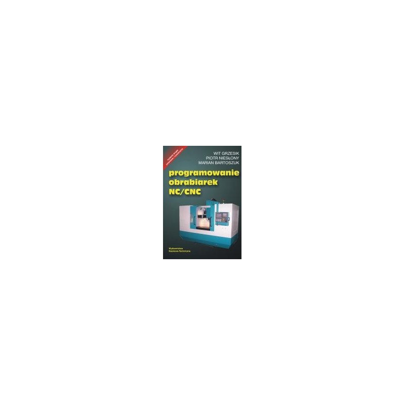
- Out-of-Stock


List of acronyms
1. Admission
2. CNC - computer numerical control
2.1. Definition and characteristics of the CNC control system
2.2. Construction and functions of the CNC
2.3. Ways of entering data / control program into the CNC
3. Methods of programming NC / CNC machine tools
3.1. Definition and classification of programming methods
3.2. Manual programming and computer aided programming
3.3. CNC Manual programming
3.4. Automatic (machine) programming
3.5. Shop-oriented programming (WOP)
3.6. Interactive programming (in CAD / CAM system)
4. Types of NC / CNC machine tool control systems
4.1. Point control
4.2. Section control
4.3. Form control (continuous)
5. Equipment for numerically controlled machine tools
5.1. Equipment for lathes and turning centers
5.2. The equipment of milling and boring machining centers
5.3. Tools for machining molds and matrices
5.4. Multifunction tools for complete machining
6. Programming machining on CNC machine tools
6.1. Structure of control programs
6.2. Machine and workpiece coordinate systems
7. Programming of CNC systems
7.1. Measurement technology in CNC machine tools
7.2. Programming the safe area
7.3. Fixed cycles
7.4. Tool offset
7.5. subroutines
7.6. Parametric programming
8. Programming supported by an external computer
8.1. Introductory information
8.2. KSP language
8.3. GTJ language
8.4. CNC Manual language
9. Computer-aided manual programming
9.1. Turning
9.2. Example
10. Automatic programming system for lathes
10.1. Characteristics of the KSPT / WIN system
10.2. Example
11. Automatic milling machine programming system
11.1. Characteristics of the KSPF / WIN system
11.2. Example
12. The GTJ-2010 system for the design of turning machining
12.1. Designing the shape of the product and semi-finished product
12.2. Designing roughing
12.3. Designing shaping and finishing machining
12.4. Designing machining with shaped and rotating tools
12.5. Application of additional commands and options
13. GTJ-2010 system for hole machining and milling design
13.1. Designing hole machining
13.2. Designing milling
13.3. Arranging treatments along with determining their order
13.4. Checking and simulating the machining process
14. GTJ-2010 system for the design of ED machining
14.1. Building a model of a cut element
14.2. Cutting design
14.3. Checking and simulating the cutting process
15. Interactive Mastercam programming system X4
15.1. Operation and permanent functions of the Mastercam system
15.2. Construction and basic functions of workpiece definition commands
15.3. Construction and basic functions of the module CAM of the Mastercam system
15.4. Defining workpiece geometry for milling - Mill
15.5. Programming example in the interactive CAD / CAM Mastercam X4 system
Literature
Index
SparkFun BlackBoard is a base plate compatible with Arduino. It is equipped with Atmega 328P microcontroller. It has 14 I / O lines (including 6 PWM channels) and 6 analogue inputs. It has a connector in accordance with the Qwiic standard. SparkFun SPX-14669
No product available!
No product available!
Advanced ADC converter module with four channels of analog inputs for Qwiic projects, offering high resolution of 24 bits and the ability to work with single-channel and differential inputs. With a programmable amplifier, the ability to select a reference voltage and support for up to 16 modules on one I2C bus, it is an ideal solution for applications requiring precise measurement of analog signals. Sparkfun SPX-23455
No product available!
No product available!
No product available!
Single-board computer with Samsung S3C2440 processor (ARM9) with 3.5 inch LCD and touchpanel
No product available!
No product available!
No product available!
No product available!
No product available!
No product available!
No product available!
No product available!
The GY-GPS6MV1 module is a board containing the U-blox NEO-6M GPS receiver system. The tile also includes RTC backup battery, antenna connector (U.FL), voltage stabilizer and UART signal outputs
No product available!
No product available!
Adafruit 1039 - Pi Holder milled aluminum case for Raspberry Pi with logo
No product available!

