
- Out-of-Stock


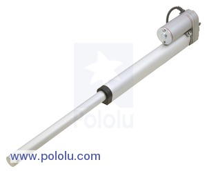
This 12 V linear actuator has a load rating of 110 lbs (51 kg) and a maximum speed of 0.6 in/s (1.6 mm/s). Limit switches at each end make the actuator easy to control over its full range of motion, and the worm drive ensures that the shaft will hold its position even when unpowered. This version has a 12-inch stroke and no potentiometer.
These low-cost linear actuators are 12V DC gearmotors that use a worm drive to move a shaft back and forth along its length. The worm drive ensures that the shaft will hold its position even when unpowered. Two limit switches safely stop the motor at either end of its range, while diodes allow it to reverse direction after reaching a limit point. The actuators are mostly metal, and the entire case is sealed to protect against dust and water (rated IP54).
 |
| Generic linear actuator with 8? stroke, fully extended. |
|---|
The linear actuators are available in a variety of lengths and with optional potentiometers that are linked to the shaft position, for use in feedback systems. They are also available in two speeds: 0.6?/s (16 mm/s) and 1.5?/s (40 mm/s). The slower 0.6?/s versions can exert a maximum force of about 110 lbs (500 N or 51 kg), while the faster 1.5?/s versions can exert up to 22 lbs (100 N or 10 kg).
You can use the table on our linear actuator category page to help you find the actuator with the combination of speed and force that best meets your project’s requirements.
Mounting brackets are available for attaching the actuators to a structure; two are required for each actuator.
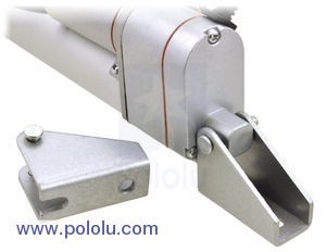 |
| Bracket connected to one end of a generic linear actuator. |
|---|
To test-drive the actuator, simply connect a power source of up to 12 V to the motor leads. Reversing the applied voltage will reverse the direction of motion. A motor controller or motor driver is required for electronic speed and direction control. We recommend our Jrk Motor Controllers for use with the feedback actuators and the Pololu Simple Motor Controller 18v7 for controlling the actuators without feedback, though many of our other motor controllers and motor drivers are capable of powering this actuator.
These actuators have a stall current of 7 A at 12 V, but they will, on average, draw far less than this when used within their load ratings. They draw around 1 A with no load and approximately 3 A at their maximum rated load, so we have found they generally work well with our lower-power jrk 21v3 motor controller with feedback (see the bottom of this page for more information using this controller for closed-loop linear actuator position control). Note, however, that the actuators can briefly draw close to their full stall current when abruptly started or on a sudden change of direction. Such current spikes can be dampened if you take steps to limit the acceleration of the actuator (many of our motor controllers offer optional acceleration limiting).
Diagrams of the linear actuators are shown below. Please note that the actuator stroke lengths in inches are nominal; the actual dimensions are specified in millimeters. The versions that include potentiometers have a larger gearbox, so their overall size and weight is larger.
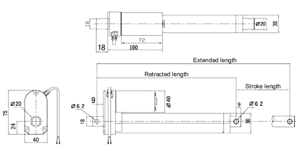 |
| Dimensions (in mm) of the generic linear actuators without feedback. |
|---|
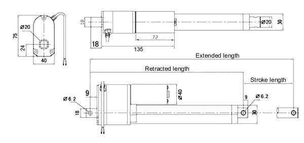 |
| Dimensions (in mm) of the generic linear actuators with feedback. |
|---|
| Stroke length | Without feedback | With feedback | ||
|---|---|---|---|---|
| Retracted length |
Extended length |
Retracted length |
Extended length | |
| 100 mm (~4?) | 205 mm | 305 mm | 240 mm | 340 mm |
| 200 mm (~8?) | 305 mm | 505 mm | 340 mm | 540 mm |
| 300 mm (~12?) | 405 mm | 705 mm | 440 mm | 740 mm |
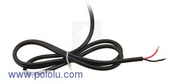
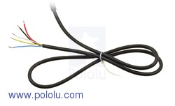
Each actuator has a 3-foot-long cable. Actuators without feedback have two unterminated, stripped power leads as shown in the left picture below. On actuators with feedback, the cable includes three additional potentiometer leads as shown in the right picture below. The potentiometer has an end-to-end resistance of 10 kΩ; the yellow and white leads are connected to its end terminals, while the blue lead is connected to its wiper. The resistance between the blue and white leads increases as the actuator extends.
|
|
The feedback feature included with our jrk motor controllers make them a great solution for precisely controlling our linear actuators with feedback. Our settings file for the jrk configuration utility makes setup easy, eliminating the need to calibrate the feedback and tune the PID constants. To get started, follow the steps below:
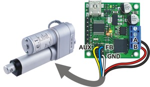 |
| Connecting a LACTxP linear actuator with feedback to a jrk 21v3 motor controller. |
|---|
While this setting file gives precise control over most of an actuator’s range, you might find decreased performance very near the extremes due to the limit switches. The voltage range covered by the potentiometer also varies among different actuators. If your project requires better control, you might need to recalibrate the feedback settings for your particular actuator.
Manufacturer BTC Korporacja sp. z o. o. Lwowska 5 05-120 Legionowo Poland sprzedaz@kamami.pl 22 767 36 20
Responsible person BTC Korporacja sp. z o. o. Lwowska 5 05-120 Legionowo Poland sprzedaz@kamami.pl 22 767 36 20
The ST25TA02KB-P is a dynamic NFC/RFID tag IC with a digital General Purpose Output (GPO), embedding a 2 Kbit EEPROM that supports NDEF tag applications for NFC Forum Type 4
No product available!
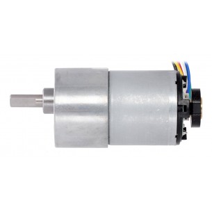
Gearmotor is a powerful 12V brushed DC motor with a 50:1 metal gearbox and an integrated quadrature encoder
No product available!
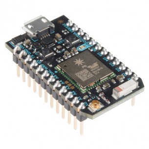
Particle Photon is an IoT module with an ARM microcontroller (Cortex-M3) and a WiFi module. The module has a 2.54 mm goldpin connector. WRL-13774
No product available!
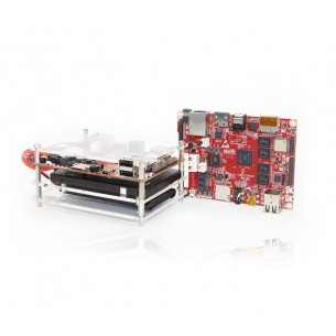
SBC computer with SoC Allwinner H8 (8-core Cortex-A7 2 GHz, PowerVR SGX544MP) equipped with: in 2 GB RAM memory, 8 GB eMMC memory, WiFi a / b / g / n, Bluetooth, SATA 2.0 interface
No product available!
No product available!
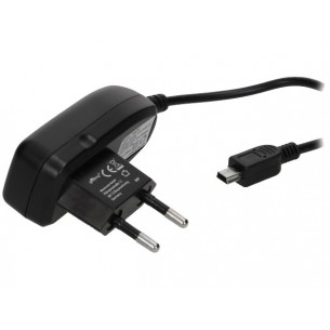
Mains power supply 5V, 1A, cable terminated with a mini-USB plug. DC / 230V AC
No product available!
The module contains two tiny cores, an x86 (Quark) and a 32-bit ARC architecture core, both clocked at 32MHz. The Intel toolchain compiles your Arduino sketches optimally across both cores to accomplish the most demanding tasks
No product available!
Particle Photon is an IoT module with an ARM microcontroller (Cortex-M3) and a WiFi module
No product available!
The RoboClaw motor controllers from Ion Motion Control (formerly Orion Robotics) can control a pair of brushed DC motors using USB serial, TTL serial, RC, or analog inputs. Integrated dual quadrature decoders make it easy to create a closed-loop speed control system. This version can supply a continuous 7.5 A per channel (15 A peak).
No product available!
No product available!
No product available!
No product available!
No product available!
ScanaPLUS is a robust, versatile and multi-application 9 Channels logic analyzer
No product available!
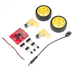
The Ardumoto Shield is an easy-to-use dual motor controller for Arduino. Combined with an Arduino, the Ardumoto makes a fantastic controller platform for RC vehicles or even small autonomous robots. KIT-13201
No product available!
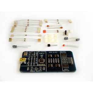
4 channel Logic Analyzer and Digital signal generator KIT, designed to decode and analyze SPI, I2C, UART, 1-WIRE and CAN
No product available!