


- Out-of-Stock


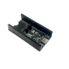
This synchronous switching step-down (or buck) regulator takes an input voltage of up to 38 V and efficiently reduces it to 5 V with an available output current of around 6 A.
These high-current step-down (buck) regulators generate a fixed 5 V output from input voltages up to 38 V. They are switching regulators (also called switched-mode power supplies (SMPS) or DC-to-DC converters) and have a typical efficiency between 80% to 95%. The available output current is a function of the input voltage and efficiency (see the Typical Efficiency and Output Current section below), but the output current can typically be as high as 6 A.
A very similar version of this regulator is available with a typical maximum output current of 9 A. The two versions of the board are difficult to tell apart visually, so the bottom silkscreen includes a blank space where you can add your own distinguishing marks or labels. You should not use the colors of the printing on the tall, cylindrical electrolytic capacitors to differentiate the two versions as these colors are subject to change. We also carry two much smaller versions of this regulator, one with a typical maximum output current of 2.5 A and one with a typical maximum output current of 5 A.
The ENABLE pin can be used to put the board in a low-power state that reduces the quiescent current to approximately 10 µA to 20 µA per volt on VIN, and a PG (power good) indicator makes it easy to monitor the state of the main power for your system. The regulator’s output voltage setting can also be lowered by adding an external resistor.
This regulator has built-in reverse-voltage protection, short-circuit protection, thermal shutdown (which typically activates at 160°C), a soft-start feature that reduces inrush current, and an under-voltage lockout that causes the regulator to turn off when the input voltage is below 4.2 V (typical).
This buck regulator has six connections: input voltage (VIN), ground (GND), output voltage (VOUT), feedback (FB), ENABLE, and power good (PG).
The input voltage, VIN, powers the regulator and can be supplied with voltages up to 38V. The effective lower limit of VIN is VOUT plus the regulator’s dropout voltage, which varies approximately linearly with the load from around 500 mV to a little over a volt (see below for a graph of the dropout voltage as a function of the load).
The output voltage, VOUT, is set to 5V by default. The output voltage can optionally be lowered by adding a resistor between the FB pin and VOUT as detailed in the Decreasing the output voltage section below.
The regulator is enabled by default: a 100 kΩ pull-up resistor on the board connects the ENABLE pin to reverse-protected VIN. The ENABLE pin can be driven low (under 0.6 V) to put the board into a low-power state. The quiescent current draw in this sleep mode is dominated by the current in the pull-up resistor from ENABLE to VIN and by the reverse-voltage protection circuit, which will draw between 10 µA and 20 µA per volt on VIN when ENABLE is held low. If you do not need this feature, you should leave the ENABLE pin disconnected.
The “power good” indicator, PG, is an open-drain output that goes low when the regulator’s output voltage falls below 90% of what it is set to (i.e. 4.5 V with the default 5 V output setting). An external pull-up resistor is required to use this pin.
The connections are labeled on the back side of the PCB, and the board offers several options for making electrical connections. The eight smaller through-holes on the ends of the board are arranged with a 0.1″ spacing for compatibility with solderless breadboards, connectors, and other prototyping arrangements that use a 0.1″ grid; you can solder pieces of the included 12×1 straight male header strip into these smaller holes. Alternatively, you can solder the included 2-pin 5mm-pitch terminal blocks to the two pairs of larger holes on the ends of the board. For the most compact installation, you can solder wires directly to the board.
The board has four 0.086″ mounting holes intended for #2 or M2 screws. The mounting holes are in the four corners of the board and are separated by 1.4″ horizontally and 0.6″ vertically. In applications where mounting screws are not used and wires are soldered directly to the board, the insulated part of the wires can be passed through the mounting holes for strain relief. The picture above shows an example of this with 20 AWG wire, which was close to the limit of what would fit through the mounting holes.
The set voltage can optionally be decreased by adding an external resistor between the FB and the neighboring VOUT pin. The equations below show how the output voltage relates to the value of an external resistor, R:
VOUT=(5.24⋅R16.2 kΩ+R+1)⋅0.8 VVOUT=(5.24⋅R16.2 kΩ+R+1)⋅0.8 V
R=(VOUT–0.8 V5 V–VOUT)⋅16.2 kΩR=(VOUT–0.8 V5 V–VOUT)⋅16.2 kΩ
For example, to get an output voltage of 3.3 V, you could put a 23.7 kΩ resistor between FB and VOUT.
The minimum VOUT for this regulator is 0.8 V. Please note that the small VOUT pin next to FB is not intended to source much current; its purpose is to provide a convenient spot for connecting a voltage-adjustment resistor.
The efficiency of a voltage regulator, defined as (Power out)/(Power in), is an important measure of its performance, especially when battery life or heat are concerns. As shown in the graph below, these switching regulators have an efficiency of 80% to 95% for most combinations of input voltage, and load.
The maximum achievable output current of the board depends on many factors, including the ambient temperature, air flow, heat sinking, and the input and output voltage. The graph below shows the maximum continuous output current this regulator can deliver with no external heat sinking or added air flow.
During normal operation, this product can get hot enough to burn you. Take care when handling this product or other components connected to it.
The dropout voltage of a step-down regulator is the minimum amount by which the input voltage must exceed the regulator’s target output voltage in order to ensure the target output can be achieved. For example, if a 5 V regulator has a 1 V dropout voltage, the input must be at least 6 V to ensure the output is the full 5 V.
The regulator generally operates at a switching frequency of around 470 kHz, but the frequency drops when encountering a light load to improve efficiency. This could make it harder to filter out noise on the output caused by switching.
| Size: | 1.6″ × 0.8″ × 0.3″1 |
|---|---|
| Weight: | 4.8 g1 |
| Minimum operating voltage: | 5 V |
|---|---|
| Maximum operating voltage: | 38 V |
| Continuous output current: | 6 A2 |
| Output voltage: | 5 V |
| Reverse voltage protection?: | Y |
| Maximum quiescent current: | 15 mA3 |
| PCB dev codes: | reg15b |
|---|---|
| Other PCB markings: | 0J8008, blank white box |
Manufacturer BTC Korporacja sp. z o. o. Lwowska 5 05-120 Legionowo Poland sprzedaz@kamami.pl 22 767 36 20
Responsible person BTC Korporacja sp. z o. o. Lwowska 5 05-120 Legionowo Poland sprzedaz@kamami.pl 22 767 36 20
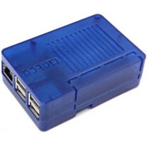
The case has openings for all outputs including the GPIO port making it a great fit for projects that are connected to external hardware.
No product available!
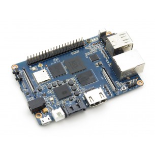
Super charged single board computer with an Octa-core processor and 2GB of RAM. Along side the elite processing unit, it features Gigabit Ethernet, 2 USB, SATA, WiFi, Bluetooth, and HDMI connection. It can run on a variety of operating systems including Android, Lubuntu, Ubuntu, Debian, and Raspbian
No product available!
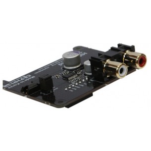
Works with the ODROID-C2 / C0 / C1+. The HiFi Shield provides both stereo RCA connectors and a 3.5mm stereo jack (all gold-plated) to connect to external amplifiers and other audio equipment
No product available!
No product available!
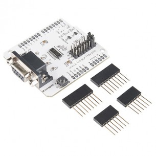
This rev of the RS232 Shield provides with the option to choose between two pins from an Arduino (D0 to D7) as software serial ports to communicate with RS232 Shield. DEV-13029
No product available!
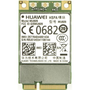
The HSPA / GSM modem card with the miniPCIe connector allows to obtain 14.4 Mbps "up" transmission speed and 5.76 Mb / s "down" transmission, working on four ranges. HUAWEI MU609
No product available!
No product available!
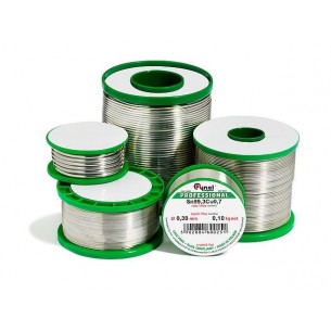
Lead-free tin Sn99Cu0.7Ag0.3 with EVO11 flux, 100 g spool, 0.25 mm diameter. Cynel SAC307-0.25/100
No product available!
The sponge is indispensable at the time of soldering, it removes tin residues and stains from the tip. Dimensions 45x60mm
No product available!
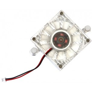
The ODROID-XU4 includes the cooling fan by default. You might need this part when you want to replace the original cooling fan
No product available!
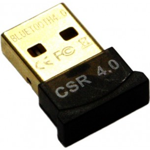
Mini USB Bluetooth dongle compatible with ODROID-C1, C1+, C0, C2 and XU3, XU4
No product available!
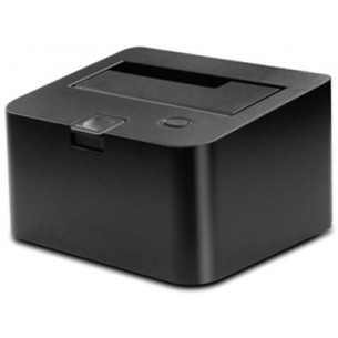
It is a USB3.0 adapter for SATA3 HDD / SSD compatible with Odroid XU4, U3 and X2. Equipped with the ASM1051E ASMedia system. The set includes a 12 V / 2 A power supply and a USB3.0 cable. Manufacturer's name: USB3.0 to SATA3 HDD / SSD interface kit
No product available!
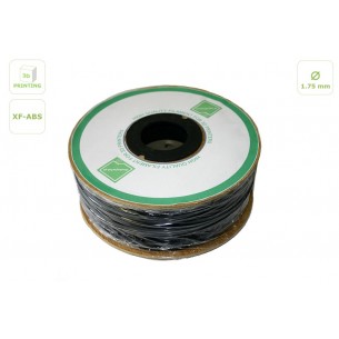
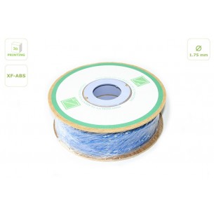
High quality XF-ABS filament for 3D printer with 1.75 mm diameter. 1 kg of wire is wound on the spool.
No product available!
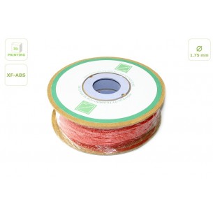
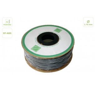
High quality XF-ABS filament for 3D printer with 1.75 mm diameter. 1 kg of wire is wound on the spool.
No product available!
High quality XF-ABS filament for 3D printer with 1.75 mm diameter. 1 kg of wire is wound on the spool.
No product available!
High quality XF-ABS filament for 3D printer with 1.75 mm diameter. 1 kg of wire is wound on the spool.
No product available!
This synchronous switching step-down (or buck) regulator takes an input voltage of up to 38 V and efficiently reduces it to 5 V with an available output current of around 6 A.