


- Out-of-Stock


Pololu - 2276
99:1 Metal Gearmotor 25Dx54L mm HP with 48 CPR Encoder
This cylindrical, 2.62" x 0.98" x 0.98" gearmotor uses a brushed DC motor with extra-strong magnets and a 98.78:1 metal gearbox to deliver a lot of power in a relatively small package. It has an integrated 48 CPR quadrature encoder on the motor shaft, which provides 4741 counts per revolution of the gearbox’s output shaft. These units have a 0.315"-long, 4 mm-diameter D-shaped output shaft. We also carry a version of this gearmotor without an encoder.
Key specs at 6 V: 100 RPM and 450 mA free-run, 160 oz-in (11.5 kg-cm) and 6 A stall.
Overview
This brushed DC gearmotor is available in high- and low-power versions in a number of gear ratios. The motor and encoder portions are available by themselves (i.e. without the gearbox), and many other gear ratios are also available without an encoder.
These motors are intended for use at 6 V. In general, these kinds of motors can run at voltages above and below this nominal voltage, so they should comfortably operate in the 3 – 9 V range, though they can begin rotating at voltages as low as 1 V. Higher voltages could start negatively affecting the life of the motor.
Details for item #2276
Exact gear ratio: 22×22×22×22×22×23/12×10×10×10×10×10≈98.78:1
Gearmotor accessories
The face plate has two mounting holes threaded for M3 screws. You can use our custom-designed 25D mm metal gearmotor bracket (shown in the picture below) to mount the gearmotor to your project via these mounting holes and the screws that come with the bracket.
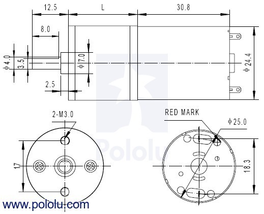
Dimensions
The diagram below shows the dimensions (in mm) of the 25D mm line of gearmotors. The value of L is shown in the table below.
Using the Encoder
A two-channel Hall effect encoder is used to sense the rotation of a magnetic disk on a rear protrusion of the motor shaft. The quadrature encoder provides a resolution of 48 counts per revolution of the motor shaft when counting both edges of both channels. To compute the counts per revolution of the gearbox output, multiply the gear ratio by 48. The motor/encoder has six color-coded, 11" (28 cm) leads terminated by a 1×6 female header with a 0.1″ pitch, as shown in the main product picture. This header works with standard 0.1″ male headers and our male jumper and precrimped wires. If this header is not convenient for your application, you can pull the crimped wires out of the header or cut the header off. The following table describes the wire functions:
| Color | Function |
| Red | motor power (connects to one motor terminal) |
| Black | motor power (connects to the other motor terminal) |
| Green | encoder GND |
| Blue | encoder Vcc (3.5 – 20 V) |
| Yellow | encoder A output |
| White | encoder B output |
The Hall sensor requires an input voltage, Vcc, between 3.5 and 20 V and draws a maximum of 10 mA. The A and B outputs are square waves from 0 V to Vcc approximately 90° out of phase. The frequency of the transitions tells you the speed of the motor, and the order of the transitions tells you the direction. The following oscilloscope capture shows the A and B (yellow and white) encoder outputs using a motor voltage of 6 V and a Hall sensor Vcc of 5 V:
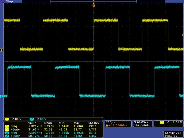
By counting both the rising and falling edges of both the A and B outputs, it is possible to get 48 counts per revolution of the motor shaft. Using just a single edge of one channel results in 12 counts per revolution of the motor shaft, so the frequency of the A output in the above oscilloscope capture is 12 times the motor rotation frequency.
Data sheet
Manufacturer BTC Korporacja sp. z o. o. Lwowska 5 05-120 Legionowo Poland sprzedaz@kamami.pl 22 767 36 20
Responsible person BTC Korporacja sp. z o. o. Lwowska 5 05-120 Legionowo Poland sprzedaz@kamami.pl 22 767 36 20
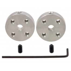
Adapter that allows you to easily mount the wheels on a motor with a shaft diameter of 4 mm using screws size 4-40. The hub fits both round and D-shaped shafts. Pololu 1081
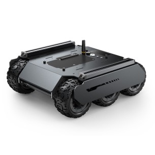
Six-wheeled mobile robot chassis designed for projects that require driving on demanding terrain. It uses a driver based on ESP32 and a set of IMU sensors. It can be easily expanded with additional elements, e.g. a robotic arm, camera or LIDAR. Waveshare UGV02 (EU)
No product available!
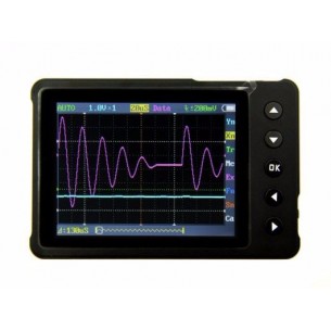
Pocket-sized digital oscilloscope with memory. Based on a microcontroller with an ARM Cortex-M3 core, it is equipped with a 320x240 pixel color display, USB port and charging function. Seeed Studio 109990013
No product available!
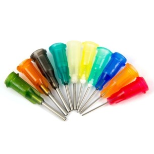
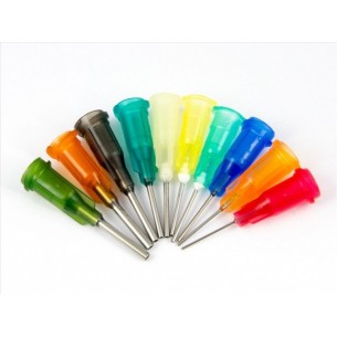
Dispensing needle for precise application of glue, flux with an internal diameter of 1.5mm and an external diameter of 1.8mm.
No product available!
Dispensing needle for precise application of glue, flux with an internal diameter of 1.2mm and an external diameter of 1.6mm.
No product available!
Dispensing needle for precise application of glue, flux with an internal diameter of 0.7mm and an external diameter of 1mm.
No product available!
Dispensing needle for precise application of glue, flux with an internal diameter of 1.37mm and an external diameter of 1.8mm.
No product available!
Dispensing needle for precise application of glue, flux with an internal diameter of 0.84mm and an external diameter of 1.25mm.
No product available!
Dispensing needle for precise application of glue, flux with an internal diameter of 0.6mm and an external diameter of 0.89mm.
No product available!
Dispensing needle for precise application of glue, flux with an internal diameter of 0.51mm and an external diameter of 0.8mm.
No product available!
Dispensing needle for precise application of glue, flux with an internal diameter of 0.41mm and an external diameter of 0.69mm.
No product available!
Dispensing needle for precise application of glue, flux with an internal diameter of 0.33mm and an external diameter of 0.6mm.
No product available!
Dispensing needle for precise application of glue, flux with an internal diameter of 0.3mm and an external diameter of 0.55mm.
No product available!
Dispensing needle for precise application of glue, flux with an internal diameter of 0.25mm and an external diameter of 0.5mm.
No product available!
Dispensing needle for precise application of glue, flux with an internal diameter of 0.24mm and an external diameter of 0.45mm.
No product available!
Dispensing needle for precise application of glue, flux with an internal diameter of 0.2mm and an external diameter of 0.4mm.
No product available!
Dispensing needle for precise application of glue, flux with an internal diameter of 0.19mm and an external diameter of 0.35mm.
No product available!
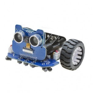
Interactive robot construction kit. based on the ESP32-S module. It can be controlled from a mobile application available on devices with Android and iOS. Additionally, it can connect to a computer via WiFi network and be programmed in Scratch and Arduino IDE. ArduCAM K0075
No product available!
Pololu - 2276