


zł146.79 tax excl.
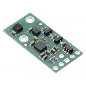
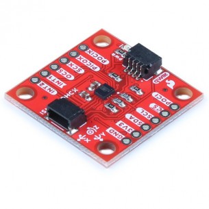
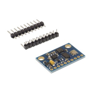
The Pololu MinIMU-9 v5 is an inertial measurement unit (IMU) that packs an LSM6DS33 3-axis gyro and 3-axis accelerometer and an LIS3MDL 3-axis magnetometer onto a tiny 0.8″ × 0.5″ board.

free shipping in Poland for all orders over 500 PLN

If your payment will be credited to our account by 11:00

Each consumer can return the purchased goods within 14 days
The Pololu MinIMU-9 v5 is a compact (0.8″ × 0.5″) board that combines ST’s LSM6DS33 3-axis gyroscope and 3-axis accelerometer and LIS3MDL 3-axis magnetometer to form an inertial measurement unit (IMU); we therefore recommend careful reading of the LSM6DS33 datasheet (1MB pdf) and LIS3MDL datasheet (2MB pdf) before using this product. These sensors are great ICs, but their small packages make them difficult for the typical student or hobbyist to use. They also operate at voltages below 3.6 V, which can make interfacing difficult for microcontrollers operating at 5 V. The MinIMU-9 v5 addresses these issues by incorporating additional electronics, including a voltage regulator and a level-shifting circuit, while keeping the overall size as compact as possible. The board ships fully populated with its SMD components, including the LSM6DS33 and LIS3MDL, as shown in the product picture.
Compared to the previous MinIMU-9 v3, the v5 version uses newer MEMS sensors that provide some increases in accuracy (lower noise and zero-rate offsets). The MinIMU-9 v5 is pin-compatible with the MinIMU-9 v3, but because it uses different sensor chips, software written for older IMU versions will need to be changed to work with the v5.
The MinIMU-9 v5 is also pin-compatible with the AltIMU-10 v5, which offers the same functionality augmented by a digital barometer that can be used to obtain pressure and altitude measurements. The AltIMU includes a second mounting hole and is 0.2″ longer than the MinIMU. Any code written for the MinIMU-9 v5 should also work with the AltIMU-10 v5.
The LSM6DS33 and LIS3MDL have many configurable options, including dynamically selectable sensitivities for the gyro, accelerometer, and magnetometer. Each sensor also has a choice of output data rates. The two ICs can be accessed through a shared I²C/TWI interface, allowing the sensors to be addressed individually via a single clock line and a single data line. Additionally, a slave address configuration pin allows users to change the sensors’ I²C addresses and have two MinIMUs connected on the same I²C bus. (For additional information, see the I²C Communication section below.)
The nine independent rotation, acceleration, and magnetic readings (sometimes called 9DOF) provide all the data needed to make an attitude and heading reference system (AHRS). With an appropriate algorithm, a microcontroller or computer can use the data to calculate the orientation of the MinIMU board. The gyro can be used to very accurately track rotation on a short timescale, while the accelerometer and compass can help compensate for gyro drift over time by providing an absolute frame of reference. The respective axes of the two chips are aligned on the board to facilitate these sensor fusion calculations. (For an example of such a system using an Arduino, see the picture below and the Sample Code section at the bottom of this page.)
The carrier board includes a low-dropout linear voltage regulator that provides the 3.3 V required by the LSM6DS33 and LIS3MDL, allowing the module to be powered from a single 2.5 V to 5.5 V supply. The regulator output is available on the VDD pin and can supply almost 150 mA to external devices. The breakout board also includes a circuit that shifts the I²C clock and data lines to the same logic voltage level as the supplied VIN, making it simple to interface the board with 5 V systems. The board’s 0.1″ pin spacing makes it easy to use with standard solderless breadboards and 0.1″ perfboards.
A 1×6 strip of 0.1″ header pins and a 1×5 strip of 0.1″ right-angle header pins are included, as shown in the picture below. You can solder the header strip of your choice to the board for use with custom cables or solderless breadboards or solder wires directly to the board itself for more compact installations. The board features two mounting holes that work with #2 or M2 screws (not included).
A minimum of four connections is necessary to use the MinIMU-9 v5: VIN, GND, SCL, and SDA. VIN should be connected to a 2.5 V to 5.5 V source, GND to 0 volts, and SCL and SDA should be connected to an I²C bus operating at the same logic level as VIN. (Alternatively, if you are using the board with a 3.3 V system, you can leave VIN disconnected and bypass the built-in regulator by connecting 3.3 V directly to VDD.)
| PIN | Description |
|---|---|
| SCL | Level-shifted I²C clock line: HIGH is VIN, LOW is 0 V |
| SDA | Level-shifted I²C data line: HIGH is VIN, LOW is 0 V |
| GND | The ground (0 V) connection for your power supply. Your I²C control source must also share a common ground with this board. |
| VIN | This is the main 2.5 V to 5.5 V power supply connection. The SCL and SDA level shifters pull the I²C bus high bits up to this level. |
| VDD | 3.3 V regulator output or low-voltage logic power supply, depending on VIN. When VIN is supplied and greater than 3.3 V, VDD is a regulated 3.3 V output that can supply up to approximately 150 mA to external components. Alternatively, when interfacing with a 2.5 V to 3.3 V system, VIN can be left disconnected and power can be supplied directly to VDD. Never supply voltage to VDD when VIN is connected, and never supply more than 3.6 V to VDD. |
| SA0 | 3.3V-logic-level input to determine I²C slave addresses of the two ICs (see below). It is pulled high by default through 10 kΩ resistor. This pin is not level-shifted and is not 5V-tolerant. |
The CS, data ready, and interrupt pins of the LSM6DS33 and LIS3MDL are not accessible on the MinIMU-9 v5. In particular, the absence of the CS pin means that the optional SPI interface of these ICs is not available. If you want these features, consider using our LSM6DS33 carrier and LIS3MDL carrier boards.
The above schematic shows the additional components the carrier board incorporates to make the LSM6DS33 and LIS3MDL easier to use, including the voltage regulator that allows the board to be powered from a single 2.5 V to 5.5 V supply and the level-shifter circuit that allows for I²C communication at the same logic voltage level as VIN. This schematic is also available as a downloadable pdf: MinIMU-9 v5 schematic (106k pdf).
The LSM6DS33’s gyro and accelerometer and the LIS3MDL’s magnetometer can be queried and configured through the I²C bus. Each of the three sensors acts as a slave device on the same I²C bus (i.e. their clock and data lines are tied together to ease communication). Additionally, level shifters on the I²C clock (SCL) and data lines (SDA) enable I²C communication with microcontrollers operating at the same voltage as VIN (2.5 V to 5.5 V). A detailed explanation of the protocols used by each device can be found in the LSM6DS33 datasheet (1MB pdf) and the LIS3MDL datasheet (2MB pdf). More detailed information about I²C in general can be found in NXP’s I²C-bus specification (1MB pdf).
The LSM6DS33 and LIS3MDL each have separate slave addresses on the I²C bus. The board connects the slave address select pins (SA0 or SA1) of the two ICs together and pulls them both to VDD through a 10 kΩ resistor. You can drive the pin labeled SA0 low to change the slave address. This allows you to have two MinIMUs (or a MinIMU v5 and an AltIMU v5) connected on the same I²C bus. The following table shows the slave addresses of the sensors:
| Sensor | Slave Address (default) | Slave Address (SA0 driven low) |
|---|---|---|
| LSM6DS33 (gyro and accelerometer) | 1101011b | 1101010b |
| LIS3MDL (magnetometer) | 0011110b | 0011100b |
Both chips on the MinIMU-9 v5 are compliant with fast mode (400 kHz) I²C standards as well as with the normal mode.
We have written a basic LSM6DS33 Arduino library and LIS3MDL Arduino library that make it easy to interface the MinIMU-9 v5 with an Arduino or Arduino-compatible board like an A-Star. They also make it simple to configure the sensors and read the raw gyro, accelerometer, and magnetometer data.
For a demonstration of what you can do with this data, you can turn an Arduino connected to a MinIMU-9 v5 into an attitude and heading reference system, or AHRS, with this Arduino program. It uses the data from the MinIMU-9 to calculate estimated roll, pitch, and yaw angles, and you can visualize the output of the AHRS with a 3D test program on your PC (as shown in a screenshot above). This software is based on the work of Jordi Munoz, William Premerlani, Jose Julio, and Doug Weibel.
The datasheets provide all the information you need to use the sensors on the MinIMU-9 v5, but picking out the important details can take some time. Here are some pointers for communicating with and configuring the LSM6DS33 and LIS3MDL that we hope will get you up and running a little bit faster:
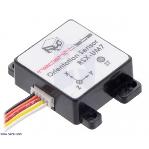
We carry several inertial measurement and orientation sensors. The table below compares their capabilities:
| Product Name | Sensors | Estimation | Other | ||||||
|---|---|---|---|---|---|---|---|---|---|
| Gyros (3x) | Accels (3x) | Mag (3x) | Altitude | Roll | Pitch | Yaw | Quaternion | Enclosure | |
| Pololu MinIMU-9 v5 |  |
|
|
||||||
| Pololu AltIMU-10 v5 | |
|
|
|
|||||
| Redshift Labs UM7-LT Orientation Sensor | |
|
|
|
|
|
|
||
| Redshift Labs UM7 Orientation Sensor | |
|
|
|
|
|
|
|
|
| Size: | 0.8″ × 0.5″ × 0.1″1 |
|---|---|
| Weight: | 0.7 g1 |
| Interface: | I²C |
|---|---|
| Minimum operating voltage: | 2.5 V |
| Maximum operating voltage: | 5.5 V |
| Axes: | pitch (x), roll (y), and yaw (z) |
| Measurement range: | ±125, ±245, ±500, ±1000, or ±2000°/s (gyro) ±2, ±4, ±8, or ±16 g (accelerometer) ±4, ±8, ±12, or ±16 gauss (magnetometer)2 |
| Supply current: | 5 mA |
| PCB dev codes: | imu04a |
|---|---|
| Other PCB markings: | 0J9486 |
Data sheet
Inertial measurement unit (IMU) and altimeter that features the same LSM6DS33 gyro and accelerometer and LIS3MDL magnetometer as the MinIMU-9 v5, and adds an LPS25H digital barometer. Pololu 2739
No product available!
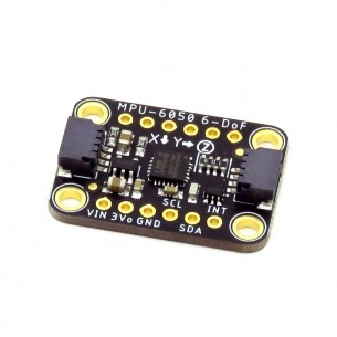
Accelerometer and gyroscope module, allows measurement of acceleration in the range of +/- 16 G and angular velocity in the range up to +/- 2000 dps. modMPU6500 (GY-6500)
No product available!
KAmodLSM303C is a module with the MEMS LSM303C chip from STMicroelectronics. The chip has a digital signal output (I2C or SPI bus) and allows measurement of accelerations and magnetic field values in three axes
GY-9255 is a 9 Degrees of Freedom (9DoF) module with the InvenSense MPU-9255 chip. It has a built-in gyroscope, accelerometer and magnetometer
No product available!
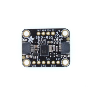
Module with 9-axis IMU sensor BNO055. It has a built-in processing chip that returns orientation in 3D space. Communicates via I2C. Adafruit 4646
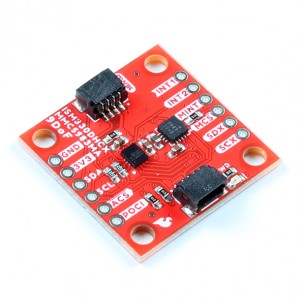
Module with 9-axis IMU. It combines the ISM330DHCX (accelerometer and gyroscope) and MMC5983MA (magnetometer) systems. Communication via the I2C interface. SparkFun SEN-19895
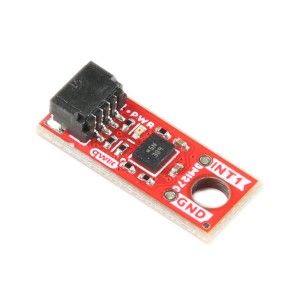
BMI270 3-axis accelerometer and gyroscope module. The chip is a low-power IMU optimised for wearables, providing precise acceleration measurement, angular velocity measurement and motion-triggered interrupt functions. Equipped with a Qwiic connector, it communicates via an I2C interface. SparkFun SEN-22398
The GY-87 module is composed of a module with MPU6050, QMC5883L and BMP180 sensors, allowing the measurement of traffic in nine axes and the measurement of atmospheric pressure. The module has a built-in 3.3 V voltage stabilizer
Module with 3-axis accelerometer and ISM330DHCX gyroscope. Equipped with a Qwiic connector, it communicates via the I2C or SPI interface. SparkFun SEN-19764
Small 10 DoF IMU module with 3-axis gyroscope and accelerometer (LSM6DSO), 3-axis magnetometer (LIS3MDL) and barometer (LPS22DF). It is equipped with an I2C interface, a voltage stabilizer and a voltage level converter. Pololu 2863
The LSM6DS33 combines a digital 3-axis accelerometer and 3-axis gyroscope into a single package. The sensor provides six independent acceleration and rotation rate readings whose sensitivities can be set in the ranges of ±2 g to ±16 g and ±125°/s to ±2000°/s, available through I²C and SPI interfaces.
6DoF module with MPU6050 (3-axis accelerometer, 3-axis gyroscope) powered with 3-5V. I2C communication interface
GY-801 is a 9DOF IMU module with L3G4200D, ADXL345, MMC5883MA and BMP180 systems. It allows you to measure the movement of the object and atmospheric pressure.
Module with 3-axis accelerometer and ISM330DHCX gyroscope. Equipped with a Qwiic connector, it communicates via the I2C interface. SparkFun SEN-20176
No product available!
The UM7 orientation sensor from Redshift Labs is an Attitude and Heading Reference System (AHRS) that contains a three-axis accelerometer, rate gyro, and magnetometer. It combines this data using an Extended Kalman Filter to produce attitude and heading estimates.
No product available!
KAmodLSM6DS3 is a module that allows measurement of acceleration and angular velocity values. It has a built-in voltage stabilizer and level translators on SDA / SCL lines, thanks to which it can be used in 2.5-5.5V voltage systems
Module with acceleration and rotational speed sensor based on the MPU-6050 system. Equipped with a STEMMA QT connector, it communicates via the I2C interface. Adafruit 3886
The Pololu MinIMU-9 v5 is an inertial measurement unit (IMU) that packs an LSM6DS33 3-axis gyro and 3-axis accelerometer and an LIS3MDL 3-axis magnetometer onto a tiny 0.8″ × 0.5″ board.